Toyota Sienna Service Manual: Inspection
1. INSPECT POWER STEERING RACK
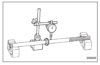
(a) Using a dial indicator, check the power steering rack for runout and for teeth wear and damage.
Maximum runout: 0.3 mm (0.012 in.) If necessary, replace the rack & pinion power steering gear assembly.
(b) Check the back surface for wear and damage.
If necessary, replace the rack & pinion power steering gear assembly.
2. INSPECT TIE ROD ASSEMBLY LH
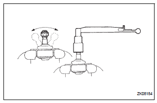
(a) Secure the tie rod assembly in a vise.
(b) Install the nut to the stud bolt.
(c) Flip the ball joint stud back and forth 5 times.
(d) Using a torque wrench, turn the nut continuously at a rate of 3 to 5 seconds per turn and take the torque reading on the 5th turn.
Torque: Turning torque 0.83 to 3.43 N*m (8.5 to 35.0 kgf*cm, 7.3 to 30.4 in.*lbf)
3. INSPECT TIE ROD ASSEMBLY RH
HINT: Perform the same procedure on the other side.
 Disassembly
1. REMOVE RETURN TUBE NO.2
(a) Using SST, remove the return tube No. 2.
SST 09023-12701
2. REMOVE STEERING LEFT TURN PRESSURE TUBE
(a) Using SST, remove the left turn pressure tube.
S ...
 Reassembly
1. INSTALL RACK STEERING PISTON RING
(a) Coat a new O-ring with power steering fluid and
install it onto the power steering rack.
(b) Expand a new rack steering piston ring with your
fingers ...
Other materials:
SRS Warning Light Remains ON
DESCRIPTION
The SRS warning light is located on the combination meter assembly.
When the SRS is normal, the SRS warning light comes on for approximately 6
seconds after the ignition
switch is turned from the LOCK position to ON position, and then goes off
automatically.
If there is a mal ...
How to proceed with
troubleshooting
HINT:
Troubleshoot in accordance with the procedures on the
following pages
1 VEHICLE BROUGHT TO WORKSHOP
2 CUSTOMER PROBLEM ANALYSIS CHECK AND SYMPTOM CHECK
3 INSPECT COMMUNICATION FUNCTION OF LARGE-SCALE MULTIPLEX
COMMUNICATION SYSTEM (BEAN)
Use the intelligent tester to check for normal ...
Monitor result information
If you use a generic scan tool, multiply the test value by
the scaling value listed below.
...
