Toyota Sienna Service Manual: Installation
1. INSTALL COMPRESSOR AND MAGNETIC CLUTCH
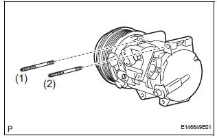
(a) Using a "TORX" socket wrench (E8), install the compressor and magnetic clutch with the 2 stud bolts.
Torque: 10 N*m (102 kgf*cm, 7.4 ft.*lbf)
HINT: Tighten the stud bolts in the order shown in the illustration.
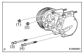
(b) Install the compressor and magnetic clutch with the 2 bolts and the 2 nuts.
Torque: 25 N*m (255 kgf*cm, 18 ft.*lbf)
HINT: Tighten the bolts and nuts in the order shown in the illustration.
(c) Connect the 2 clamps and wire harness.
(d) Connect the connector.
2. INSTALL SUCTION HOSE SUB-ASSEMBLY
(a) Remove the attached vinyl tape from the hose.
(b) Apply sufficient compressor oil to a new O-ring and the fitting surface of the compressor and magnetic clutch.
Compressor oil: ND-OIL 8 or equivalent
(c) Install the O-ring onto the suction hose subassembly.
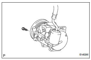
(d) Install the suction hose sub-assembly onto the compressor and magnetic clutch with the bolt.
Torque: 5.4 N*m (55 kgf*cm, 48 in.*lbf)
3. INSTALL DISCHARGE HOSE SUB-ASSEMBLY
(a) Remove the attached vinyl tape from the hose.
(b) Apply sufficient compressor oil to a new O-ring and the fitting surface of the compressor and magnetic clutch.
Compressor oil: ND-OIL 8 or equivalent
(c) Install the O-ring onto the discharge hose subassembly.
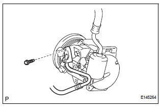
(d) Install the discharge hose sub-assembly onto the compressor and magnetic clutch with the bolt.
Torque: 5.4 N*m (55 kgf*cm, 48 in.*lbf)
4. INSTALL RADIATOR AND FAN ASSEMBLY
(See page CO-39)
5. INSTALL V-RIBBED BELT (See page EM-7)
6. INSTALL FRONT FENDER APRON SEAL RH (See page EM-62)
7. INSTALL FRONT WHEEL RH
8. CHARGE WITH REFRIGERANT (See page AC-173)
9. WARM UP ENGINE
10. INSPECT FOR REFRIGERANT LEAK (See page AC- 173)
 Reassembly
1. INSTALL MAGNETIC CLUTCH ASSEMBLY
(a) Install the magnetic clutch stator while aligning the
protrusion on the stator with the notch on the air
compressor assembly as shown in the illustration ...
 Condenser
COMPONENTS
...
Other materials:
Unlocking and locking the doors from the inside
Door lock switch
Locks all the doors
Unlocks all the doors
Inside lock button
Locks the door
Unlocks the door
The front doors can be opened
by pulling the inside handle
even if the lock buttons are in
the lock position. ...
Front wiper rubber
COMPONENTS
REMOVAL
1. REMOVE FRONT WIPER BLADE
Remove the front wiper blade from the front wiper
arm LH.
NOTICE:
Do not fold down the front wiper arm with the
front wiper blade being removed from it.
2. REMOVE FRONT WIPER RUBBER
Remove the front wiper rubber from th ...
Replacing light bulbs
Headlight low beams (halogen bulb)
For left side only: Open the fuse box cover.
Unplug the connector while
pushing the lock release.
Turn the bulb base counterclockwise.
Install a new light bulb.
Align the 3 tabs on the light bulb
with the mounting, and insert.
...
