Toyota Sienna Service Manual: Reassembly
1. INSTALL MAGNETIC CLUTCH ASSEMBLY
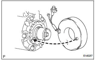
(a) Install the magnetic clutch stator while aligning the protrusion on the stator with the notch on the air compressor assembly as shown in the illustration.
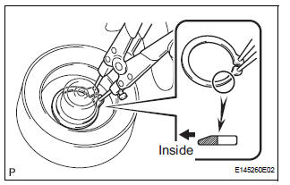
(b) Using a snap ring expander, install a new snap ring with the chamfered side facing up.
NOTICE: Take care not to damage the seal cover of the bearing when installing the snap ring
(c) Install the screw and connect the connector.
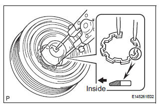
(d) Using a snap ring expander, install the magnetic clutch rotor and a new snap ring with the chamfered side facing up.
NOTICE:
- Do not expand the snap ring by more than 35.5 mm (1.39 in.) when installing it.
- Do not damage the seal cover of the bearing when installing the snap ring.
(e) Install the magnet clutch washer and the magnet clutch hub.
NOTICE: Do not change the combination of the magnetic clutch washers used before disassembly.
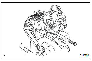
(f) Using vise pliers, hold the magnetic clutch hub and install the bolt.
Torque: 18 N*m (183 kgf*cm, 13 ft.*lbf)
NOTICE: Make sure that there is no foreign matter or oil on the compressor shaft, bolt, and clutch hub.
 Inspection
1. INSPECT MAGNETIC CLUTCH CLEARANCE
(a) Set the dial indicator to the magnetic clutch hub.
(b) Connect the battery positive lead to the terminal 1 of
the magnet clutch connector and the nega ...
 Installation
1. INSTALL COMPRESSOR AND MAGNETIC CLUTCH
(a) Using a "TORX" socket wrench (E8), install the
compressor and magnetic clutch with the 2 stud
bolts.
Torque: 10 N*m (102 kgf*cm, 7.4 ft. ...
Other materials:
Safety Connect LED light Indicators
When the engine switch is turned to the “ON” position (vehicles without
a smart key system) or IGNITION ON mode (vehicles with a smart
key system), the red indicator light comes on for 2 seconds then turns
off. Afterward, the green indicator light comes on, indicating that the
service is act ...
Removal
HINT:
Use the same procedures for the RH side and LH side.
The procedures listed below are for the LH side.
1. PRECAUTION
CAUTION:
Be sure to read "PRECAUTION" thoroughly before servicing.
2. DISCONNECT CABLE FROM NEGATIVE BATTERY
TERMINAL
CAUTION:
Wait for 90 se ...
Mute Signal Circuit between Radio Receiver and Stereo Component
Amplifier
DESCRIPTION
This circuit sends a signal to the stereo component amplifier to mute noise.
Because of that, the noise
produced by changing the sound source ceases.
If there is an open in the circuit, noise can be heard from the speakers when
changing the sound source.
If there is a short i ...
