Toyota Sienna Service Manual: Inspection
1. INSPECT HEATED OXYGEN SENSOR (for Bank 1 Sensor 2)
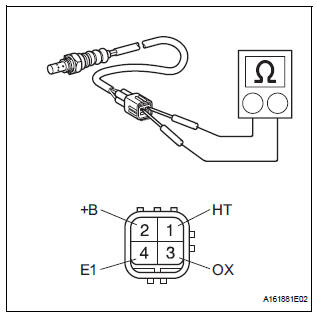
(a) Measure the resistance of the sensor.
Standard resistance
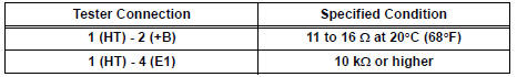
If the resistance is not as specified, replace the sensor.
2. INSPECT HEATED OXYGEN SENSOR (for Bank 2 Sensor 2)
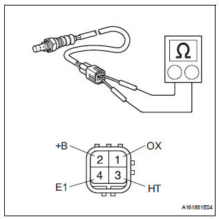
(a) Measure the resistance of the sensor.
Standard resistance
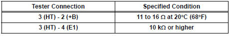
If the resistance is not as specified, replace the sensor.
Installation
1. INSTALL HEATED OXYGEN SENSOR (for Bank 2 Sensor 2)
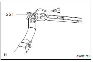
(a) Using SST, install the heated oxygen sensor to the front exhaust pipe.
SST 09224-00010
Torque: 40 N*m (408 kgf*cm, 30 ft.*lbf) for use with SST 44 N*m (449 kgf*cm, 32 ft.*lbf) for use without SST
HINT:
- Use a torque wrench with a fulcrum length of 30 cm (11.81 in.).
- Make sure that SST and a wrench are connected in a straight line.
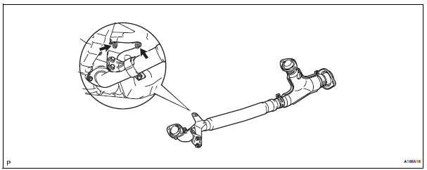
2. INSTALL FRONT EXHAUST PIPE ASSEMBLY
(a) Check the compression springs.
(1) Check the compression springs using vernier calipers
Specified length: 38.86 mm (1.5299 in.)
HINT: If the result is not as specified, replace the compression spring.
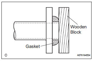
(b) Install the gasket.
(1) Install a new gasket by hand onto the front exhaust pipe assembly.
(2) Using a plastic hammer and wooden block, tap in the new gasket until its surface is flush with the front exhaust pipe.
NOTICE:
|
(c) Install 2 new gaskets to the front exhaust pipe assembly.
(d) Install the front exhaust pipe assembly with the 4 nuts.
Torque: 62 N*m (632 kgf*cm, 46 ft.*lbf)
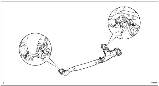
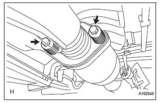
(e) Install the front exhaust pipe assembly with the 2 compression springs and 2 bolts.
Torque: 43 N*m (438 kgf*cm, 32 ft.*lbf) (f) Install the No. 1 exhaust pipe support bracket with 2 new nuts.
Torque: 21 N*m (214 kgf*cm, 15 ft.*lbf)
(g) Connect the heated oxygen sensor (for Bank 2 sensor 2) connector.
3. INSTALL HEATED OXYGEN SENSOR (for Bank 1 Sensor 2)
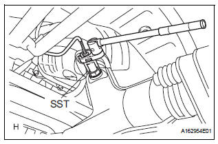
(a) Using SST, install the heated oxygen sensor.
SST 09224-00010
Torque: 40 N*m (408 kgf*cm, 30 ft.*lbf) for use with SST
44 N*m (449 kgf*cm, 32 ft.*lbf) for use without SST
HINT:
- Use a torque wrench with a fulcrum length of 30 cm (11.81 in.).
- Make sure that SST and a wrench are connected in a straight line.
b) Connect the heated oxygen sensor (for Bank 1 Sensor 2) connector.
4. CONNECT CABLE TO NEGATIVE BATTERY TERMINAL
5. INSPECT FOR EXHAUST GAS LEAK
 Heated oxygen sensor (for 2wd)
Components
Removal
1. DISCONNECT CABLE FROM NEGATIVE BATTERY
TERMINAL
CAUTION:
Wait at least 90 seconds after disconnecting the
cable from the nagative (-) battery terminal to
...
 Heated oxygen sensor (for 4wd)
Components
...
Other materials:
Engine immobilizer
system
The vehicle’s keys have built-in transponder chips that prevent
the engine from starting if a key has not been previously registered
in the vehicle’s on-board computer.
Never leave the keys inside the vehicle when you leave the vehicle.
This system is designed to help prevent vehicle the ...
Indicator Circuit
DESCRIPTION
This system has two indicator lights. One of the indicator lights is built
into the fold seat switch. This
indicator light receives power from the fold seat control ECU. It comes on or
blinks when the system
detects that an object is caught or when the seat operation conditions ar ...
If a warning message is displayed
If a warning message is shown on the multi-information display,
stay calm and perform the following actions:
Master warning light
The master warning light also comes on or flashes in order to indicate that
a message is currently being displayed on the multi-information display.
Multi- ...
