Toyota Sienna Service Manual: Heated oxygen sensor (for 2wd)
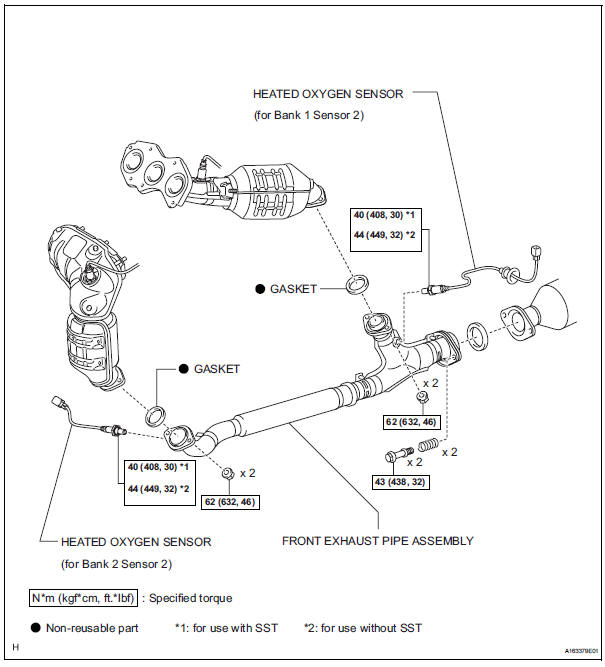
Components
Removal
1. DISCONNECT CABLE FROM NEGATIVE BATTERY TERMINAL
| CAUTION: Wait at least 90 seconds after disconnecting the cable from the nagative (-) battery terminal to prevent airbag and seat belt pretensioner activation. |
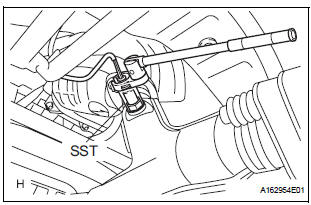
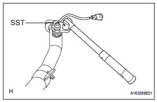
2. REMOVE HEATED OXYGEN SENSOR (for Bank 1 Sensor 2)
(a) Disconnect the sensor connector under the center console.
(b) Using SST, remove the heated oxygen sensor.
SST 09224-00010
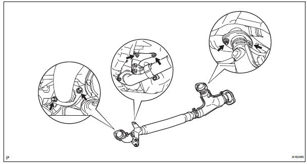
3. REMOVE FRONT EXHAUST PIPE ASSEMBLY
(a) Disconnect the heated oxygen sensor (for Bank 2 Sensor 2) connector.
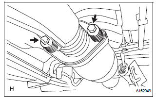
(b) Remove the 2 bolts and 2 compression springs.
(c) Remove the 6 nuts and front exhaust pipe assembly.
4. REMOVE HEATED OXYGEN SENSOR (for Bank 2 Sensor 2)
(a) Using SST, remove the heated oxygen sensor from the front exhaust pipe assembly.
SST 09224-00010
 Installation
1. INSTALL AIR FUEL RATIO SENSOR (for Bank 2
Sensor 1)
(a) Using SST, install the sensor to the exhaust
manifold LH.
SST 09224-00010
Torque: 40 N*m (408 kgf*cm, 30 ft.*lbf) for use
with SST
...
 Inspection
1. INSPECT HEATED OXYGEN SENSOR (for Bank 1
Sensor 2)
(a) Measure the resistance of the sensor.
Standard resistance
If the resistance is not as specified, replace the
sensor.
2. INSPECT HE ...
Other materials:
No. 1 Speaker with box
COMPONENTS
ON-VEHICLE INSPECTION
1. INSPECT NO.1 SPEAKER WITH BOX
HINT:
Remove interior parts so that the No.1 speaker with box
can be seen.
Check the speaker installation.
OK:
The speaker is securely installed.
If the result is not as specified, reinstall the No.1
s ...
Removal
1. PRECAUTION
HINT:
See page RS-1
2. DISCONNECT BATTERY NEGATIVE TERMINAL
Wait for 90 seconds after disconnecting the battery
terminal to prevent the airbag working.
3. PLACE FRONT WHEELS FACING STRAIGHT AHEAD
4. REMOVE STEERING WHEEL COVER LOWER NO.2
(See page RS-424)
5. REMOVE STEERING WH ...
Tire Pressure Warning Light Circuit
DESCRIPTION
If the ECU detects trouble, the tire pressure warning light blinks (comes on
after blinking for 1 minute) and
tire pressure monitor is cancelled at the same time. At this time, the ECU
records a DTC in the memory.
Connect terminals TC and CG of DLC3 to make the tire pressure war ...
