
Toyota Sienna Service Manual: Heated oxygen sensor (for 4wd)
Components
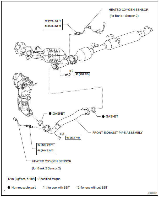
 Inspection
1. INSPECT HEATED OXYGEN SENSOR (for Bank 1
Sensor 2)
(a) Measure the resistance of the sensor.
Standard resistance
If the resistance is not as specified, replace the
sensor.
2. INSPECT HE ...
 Removal
1. DISCONNECT CABLE FROM NEGATIVE BATTERY
TERMINAL
2. REMOVE HEATED OXYGEN SENSOR (for Bank 1
Sensor 2)
(a) Disconnect the sensor connector under the center
console.
(b) Using SST, remove the ...
Other materials:
Reassembly
1. INSTALL LIGHT CONTROL ECU (DISCHARGE HEADLIGHT)
Install a new headlight leveling motor base packing.
Install the headlight leveling motor assembly as
shown in the illustration.
Connect the connector with the claw
Install the light control ECU with the 2 ...
VIN not Programmed or Mismatch - ECM / PCM
DESCRIPTION
DTC P0630 is set when the Vehicle Identification Number (VIN) is not stored
in the Engine Control Module
(ECM) or the input VIN is not accurate. Input the VIN with the intelligent
tester.
MONITOR STRATEGY
TYPICAL ENABLING CONDITIONS
TYPICAL MALFUNCTION THRESHOLDS ...
Inspection
1. Inspect heated oxygen sensor (for bank 1
sensor 2)
(a) Measure the resistance of the sensor.
Standard resistance
If the resistance is not as specified, replace the
sensor.
2. HEATED OXYGEN SENSOR (for Bank 2 Sensor 2)
(a) Measure the resistance of the sensor.
Standard resistance ...
