Toyota Sienna Service Manual: Inspection
1. Inspect no. 3 Intake air control valve assembly
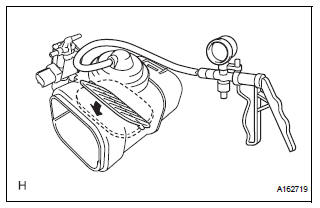
(A) inspect actuator operation.
(1) With 26.7 Kpa (200 mm hg, 7.9 In. Hg) of vacuum applied to the actuator, check that the actuator rod moves.
(2) One minute after applying the vacuum, check that the actuator rod does not return.
(3) If the operation is not as specified, replace the no. 3 Intake air control valve.
Installation
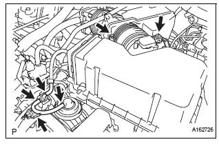
1. INSTALL NO. 3 INTAKE AIR CONTROL VALVE ASSEMBLY
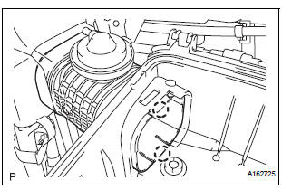
(a) Engage the 2 claws and install the No. 3 intake air control valve assembly.
2. INSTALL AIR CLEANER CAP SUB-ASSEMBLY
(a) Install the air cleaner filter element, and air cleaner cap sub-assembly with the 2 bolts.
Torque: 5.0 N*m (50 kgf*cm, 44 in.*lbf)
(b) Connect the 3 vacuum hoses.
(c) Tighten the bolt, connect the 2 connectors, and install the 2 vacuum hoses.
3. INSTALL NO. 2 AIR CLEANER INLET (See page EM- 60)
 Removal
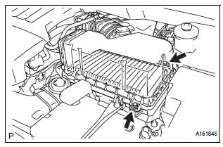
1. Remove no. 2 Air cleaner inlet (see page em-
28)
2. Remove air cleaner cap sub-assembly
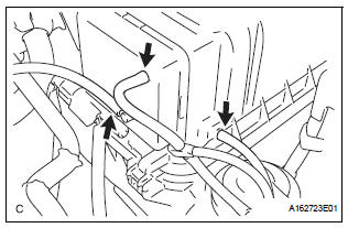
(a) Disconnect the 3 vacuum hoses.
(b) Loosen the bolt, disconnect the 2 connectors, and
remove ...
 Vacuum tank
On-vehicle inspection
1. Inspect air cleaner cap sub-assembly
(A) check that air flows from port b to port a.
(B) apply 60 kpa (450 mm hg, 18 in. Hg) of vacuum to
port b. Check that there is ...
Other materials:
Removal
1. PRECAUTION
CAUTION:
Be sure to read "PRECAUTION" thoroughly before
servicing.
2. DISCONNECT CABLE FROM NEGATIVE BATTERY
TERMINAL
CAUTION:
Wait for 90 seconds after disconnecting the cable to
prevent the airbag working.
3. REMOVE STEERING WHEEL NO.3 COVER LOWER
Using a ...
Installation
1. INSTALL REAR DIFFERENTIAL SIDE GEAR SHAFT BOLT
(a) Install the bolt tightening the nut through the plate
washer.
2. INSTALL REAR DRIVE SHAFT ASSEMBLY LH
HINT:
(See page DS-26)
3. INSTALL REAR AXLE SHAFT NUT LH
HINT:
(See page DS-26)
4. INSTALL REAR SPEED SENSOR LH
HINT:
(See page D ...
Differential system
PRECAUTION
NOTICE:
When disconnecting the negative (-) battery terminal,
initialize the following systems after the terminal is
reconnected.
1. Before disassembly, clean the outside of the rear
differential assembly and remove any sand or mud to
prevent it from entering the inside of the as ...
