
Toyota Sienna Service Manual: Removal
1. Remove no. 2 Air cleaner inlet (see page em- 28) 2. Remove air cleaner cap sub-assembly
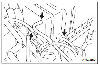
(a) Disconnect the 3 vacuum hoses.
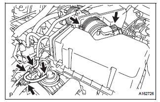
(b) Loosen the bolt, disconnect the 2 connectors, and remove the 2 vacuum hoses.
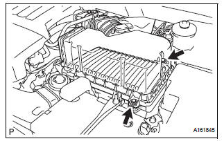
(c) Remove the 2 bolts, air cleaner cap sub-assembly, and air cleaner filter element.
3. REMOVE NO. 3 INTAKE AIR CONTROL VALVE ASSEMBLY
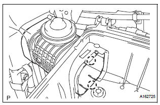
(a) Disengage the 2 claws and remove the No. 3 intake air control valve assembly.
 On-vehicle inspection
1. Inspect intake air surge tank assembly
(A) inspection procedure when applying voltage
between the terminals:
(1) Disconnect the connector from the intake air
control valve.
(2) Apply bat ...
 Inspection
1. Inspect no. 3 Intake air control valve
assembly
(A) inspect actuator operation.
(1) With 26.7 Kpa (200 mm hg, 7.9 In. Hg) of
vacuum applied to the actuator, check that the
actuator rod m ...
Other materials:
How to proceed with
troubleshooting
NOTICE:
DTCs for the CAN communication system are as follows:
U0073, U0100, U0122, U0123, U0124, U0126 and U1101.
HINT:
If U0235 or U1102 is output alone, the CAN communication is
normal
1 CHECK AND CLEAR DTCS
HINT:
CAN communication DTCs are output when there is an
open or short in any ...
Communication Error of Yaw Rate Sensor
DTC U0123 Communication Error of Yaw Rate Sensor
DESCRIPTION
This circuit detects the yaw rate of the vehicle and transmits its signal to
the skid control ECU and
distance control ECU.
DTC No.
DTC Detection Condition
Trouble Area
U0123
While the dynamic ...
Audio system operation buttons
“AUDIO� button
Display the “Select Audio Source� screen or audio top screen.
“SETUP� button
Press this button to customize the function settings.
“CAR� button
Press this button to access the vehicle information.
button
Press this button to access the Blue ...
