Toyota Sienna Service Manual: Inspection
1. INSPECT OIL PUMP RELIEF VALVE
(a) Coat the relief valve with engine oil and check that it falls smoothly into the valve hole under its own weight.
If the valve does not fall smoothly, replace the relief valve. If necessary, replace the oil pump assembly.
2. INSPECT OIL PUMP ROTOR SET
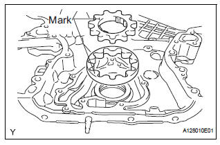
(a) Install the rotors to the timing chain cover with the rotors' marks facing outward. Check that the rotors rotate smoothly.
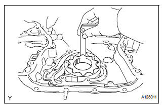
(b) Check the tip clearance.
(1) Using a feeler gauge, measure the clearance between the drive and driven rotors, as shown in the illustration.
Tip clearance 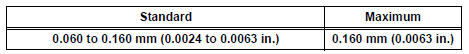
If the clearance is greater than the maximum, replace the drive and driven rotors.
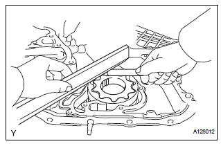
(c) Check the side clearance.
(1) Using a feeler gauge and precision straightedge, measure the clearance between the rotors and precision straightedge, as shown in the illustration.
Side clearance 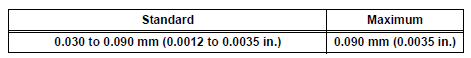
If the side clearance is greater than the maximum, replace the timing chain cover.
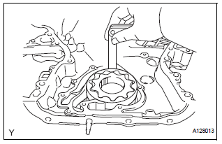
(d) Check the body clearance.
(1) Using a feeler gauge, measure the clearance between the timing chain cover and driven rotor, as shown in the illustration.
Body clearance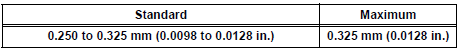
If the body clearance is greater than the maximum, replace the timing chain cover.
 Disassembly
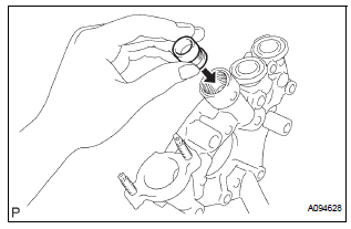
1. REMOVE OIL PUMP RELIEF VALVE
(A) using a 27 mm socket wrench, remove the relief
valve plug.
(B) remove the valve spring and oil pump relief valve.
2. REMOVE OIL PUMP COVER
(a) Remove ...
 Reassembly
1. INSTALL OIL PUMP COVER
(a) Coat the drive and driven rotors with engine oil and
place them into the timing chain cover with the
marks facing outward (oil pump cover side). Check
that the ro ...
Other materials:
DTC check / clear
1. CHECK DTC
Connect the intelligent tester to the Controller Area
Network Vehicle Interface Module (CAN VIM). Then
connect the CAN VIM to the DLC3.
Turn the ignition switch on.
Turn the tester ON.
Enter the following menu items: DIAGNOSIS / OBD/
MOBD / IM ...
Sound Signal Circuit between Radio and Navigation Assembly and
Television Display Assembly
DESCRIPTION
The television display assembly sends an RSE sound signal to the radio and
navigation assembly through
this circuit. The sound signal that has been sent is amplified by the stereo
component amplifier, and then
is sent to the speakers.
If there is an open or short in the circuit ...
Disposal
HINT:
When scrapping a vehicle equipped with the SRS or
disposing of the front passenger airbag assembly, be sure to
deploy the airbag first in accordance with the procedure
described below. If any abnormality occurs with airbag
deployment, contact the SERVICE DEPT. of the TOYOTA
MOTOR SALES, ...
