Toyota Sienna Service Manual: Installation
1. INSTALL REAR DRIVE SHAFT ASSEMBLY LH
(a) Install the drive shaft to the axle carrier.
NOTICE: Be careful not to damage the boot and ABS speed sensor rotor to the drive shaft and oil seal of the axle hub bearing.
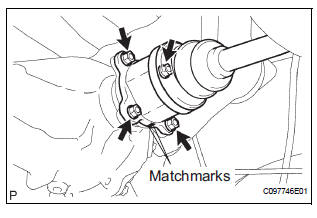
(b) Align the matchmarks and connect the drive shaft to the side gear shaft.
NOTICE: Be careful not to damage the boots and end cover.
(c) Install the drive shaft with the 4 nuts and washers.
Torque: 56 N*m (571 kgf*cm, 41 ft.*lbf)
2. INSTALL REAR AXLE SHAFT NUT
(a) Install a new axle shaft nut.
Torque: 216 N*m (2,200 kgf*cm, 159 ft.*lbf) (b) Using a chisel and hammer, stake the axle shaft nut.
3. INSTALL TAIL EXHAUST PIPE ASSEMBLY (See page EX-12)
4. INSTALL REAR SPEED SENSOR
(a) Install the speed sensor with the bolt.
Torque: 8.0 N*m (82 kgf*cm, 71 in.*lbf)
HINT:
- Be careful not to damage the speed sensor.
- Prevent foreign matter from adhering to the speed sensor.
- Do not twist the sensor wire when installing the sensor.
5. INSTALL REAR WHEEL Torque: 103 N*m (1,050 kgf*cm, 76 ft.*lbf)
6. CHECK FOR EXHAUST GAS LEAK
7. CHECK ABS SPEED SENSOR SIGNAL
HINT:
- for ANTI-LOCK BRAKE SYSTEM: (See page BC-3)
- for VEHICLE STABILITY CONTROL SYSTEM: (See page BC-72)
 Reassembly
1. INSTALL REAR DRIVE SHAFT OUTBOARD JOINT BOOT
HINT:
Before install the boot, wrap the spline of the outboard
joint shaft with vinyl tape to prevent the boot from
bearing damaged.
(a) Instal ...
 Differential
...
Other materials:
Removal
HINT:
Remove the RH side by the same procedure as the LH side.
1. REMOVE REAR WHEEL
2. REMOVE QUARTER TRIM PANEL ASSEMBLY
FRONT LH
HINT:
Remove the LH side by the same procedure as the RH
side (See page IR-9).
3. REMOVE REAR SPEED SENSOR
(a) Disconnect the speed sensor connector, and pu ...
Data list / active test
1. DATA LIST
The wireless door lock control data list can be
displayed while the intelligent tester is connected to
the DLC3 with the ignition switch in the ON position.
Follow the prompts on the tester screen to access
the DATA LIST.
BODY:
2. ACTIVE TEST
HINT:
Performing the ACT ...
Situations when it is necessary to contact dealers before towing
The following may indicate a problem with your transaxle. Contact
your Toyota dealer or commercial towing service before towing.
The engine is running but the vehicle does not move.
The vehicle makes an abnormal sound
Towing with a sling-type truck
Do not tow with a sling-type truck
to p ...
