Toyota Sienna Service Manual: Reassembly
1. INSTALL SHOCK ABSORBER ASSEMBLY FRONT LH
2. INSTALL FRONT COIL SPRING INSULATOR LOWER LH
(a) Install the front coil spring insulator lower LH onto the shock absorber assembly front LH.
3. INSTALL FRONT SPRING BUMPER LH
(a) Install the front spring bumper LH to the piston rod.
4. INSTALL FRONT COIL SPRING LH
(a) Using SST, compress the front coil spring LH.
SST 09727-30021 (09727-00010, 09727-00021, 09727-00031)
NOTICE: Do not use an impact wrench. It will damage the SST.
HINT: Use 2 SST of the same type.
(b) Install the front coil spring LH to the shock absorber assembly front LH.
HINT: Fit the front coil spring insulator lower LH into the gap of the shock absorber assembly front LH.
5. INSTALL FRONT COIL SPRING INSULATOR UPPER LH
(a) Install the front coil spring insulator upper LH as shown in the illustration.
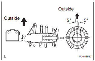
6. INSTALL FRONT COIL SPRING SEAT UPPER LH
(a) Install the front coil spring seat upper LH to the shock absorber assembly front LH with the mark facing to the outside of the vehicle.
7. INSTALL FRONT SUSPENSION SUPPORT LH BEARING
(a) Install the front suspension support LH bearing.
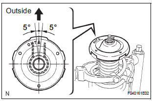
8. INSTALL FRONT SUSPENSION SUPPORT SUBASSEMBLY LH
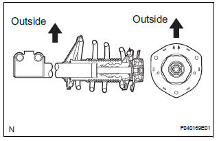
(a) Install the front suspension support sub-assembly LH with the mark facing to the outside of the vehicle.
(b) Temporarily tighten a new lock nut.
 Inspection
1. INSPECT SHOCK ABSORBER ASSEMBLY FRONT LH
(a) Compress and extend the shock absorber rod and
check that there is no unusual resistance or unusual
sound during operation.
If there is any ab ...
 Installation
1. INSTALL FRONT SHOCK ABSORBER WITH COIL SPRING
(a) Install the front shock absorber with coil spring as
shown in the illustration.
(b) Install the 3 nuts to the upper side of the front shoc ...
Other materials:
Speaking on the phone
The following screen is displayed when speaking on the phone.
To adjust the call volume
Select “-” or “+”. You can also adjust the volume using the steering
switches or the volume knob.
To prevent the other party from hearing your voice
Select “Mute”.
Inputting tones
When usin ...
Disassembly
1. REMOVE REAR SEAT LEG COVER LH
Remove the 2 screws and seat leg cover.
2. REMOVE REAR SEAT LEG COVER RH
Remove the 2 screws and seat leg cover.
3. REMOVE REAR SEAT LEG SIDE COVER LH
Remove the 2 screws and leg side cover.
4. REMOVE LH SEAT REAR SEAT LOCK COVE ...
Reverse Signal Circuit
DESCRIPTION
The radio and navigation assembly receives a reverse signal from the
park/neutral position switch and
information about the GPS antenna, and then adjusts vehicle position.
WIRING DIAGRAM
INSPECTION PROCEDURE
1 INSPECT RADIO AND NAVIGATION ASSEMBLY
Disconnect the radio ...
