Toyota Sienna Service Manual: Installation
1. INSTALL BRAKE VACUUM CHECK VALVE ASSEMBLY
(a) Install the brake vacuum check valve assembly and check valve grommet to the brake booster assembly.
2. INSTALL BRAKE BOOSTER GASKET
(a) Install a new brake booster gasket to the brake booster with master cylinder.
3. INSTALL BRAKE MASTER CYLINDER ASSEMBLY
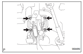
(a) Install the brake booster assembly with the 4 nuts.
Torque: 13 N*m (130 kgf*cm, 9 ft.*lbf) (b) Slide the clip and connect the brake master cylinder reservoir hose to the brake master cylinder union.
(c) Slide the clip and connect the vacuum hose from the brake vacuum check valve assembly.
4. INSTALL PUSH ROD PIN
(a) Install the push rod pin to the brake booster push rod.
5. INSTALL BRAKE LINE
(a) Install the front brake tube No. 1, front brake tube No. 2, front brake tube No. 3 and front brake tube No. 4.
Torque: 15 N*m (155 kgf*cm, 11 ft.*lbf) (b) Install the rear brake tube No. 1and rear brake tube No. 2.
Torque: 15 N*m (155 kgf*cm, 11 ft.*lbf)
6. INSTALL BRAKE ACTUATOR ASSEMBLY (w/o VSC) SST 09023-00101
HINT: See page BC-184
7. INSTALL ABS & TRACTION ACTUATOR ASSEMBLY (w/ VSC) SST 09023-00101
HINT: See page BC-179.
8. INSTALL AIR CLEANER ASSEMBLY WITH HOSE
9. FILL RESERVOIR WITH BRAKE FLUID (See page BR- 3)
10. BLEED BRAKE MASTER CYLINDER (See page BR-3)
11. BLEED BRAKE LINE (See page BR-4)
12. BLEED BRAKE ACTUATOR (w/ VSC) (See page BR- 4)
13. CHECK FLUID LEVEL IN RESERVOIR (See page BR- 7)
14. CHECK BRAKE FLUID LEAKAGE
15. INSTALL INSTRUMENT PANEL SAFETY PAD INSERT SUB-ASSEMBLY NO. 1
(a) Install the instrument panel safety pad insert subassembly No. 1 with the 4 bolts.
16. INSTALL INSTRUMENT PANEL FINISH PANEL SUBASSEMBLY LOWER LH
(a) Install the instrument panel finish panel subassembly lower LH with the 2 bolts.
17. INSTALL COWL SIDE TRIM BOARD LH
(a) Install the cowl trim board plate LH with the nut.
18. INSTALL FRONT DOOR SCUFF PLATE LH
19. INSTALL COWL TOP PANEL SUB-ASSEMBLY OUTER FRONT
20. INSTALL FRONT WHEEL Torque: 103 N*m (1,050 kgf*cm, 76 ft.*lbf)
21. INSPECT BRAKE PEDAL HEIGHT (See page BR-9)
22. CHECK BRAKE ACTUATOR WITH INTELLIGENT
TESTER 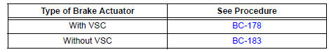
 Inspection
1. INSPECT BRAKE VACUUM CHECK VALVE ASSEMBLY
(a) Check the vacuum check valve.
(1) Slide the clip and disconnect the vacuum hose.
(2) Remove the vacuum check valve.
(3) Check that there ...
 Front brake
COMPONENTS
...
Other materials:
Eject Error/ Elevator Error/ Clamp Error/ Eject Error/ Elevator Error/ Clamp
Error
DTC 62-45 Eject Error
DTC 62-51 Elevator Error
DTC 62-52 Clamp Error
DTC 63-45 Eject Error
DTC 63-51 Elevator Error
DTC 63-52 Clamp Error
DESCRIPTION
DTC No.
DTC Detecting Condition
Trouble Area
62-45
Disc cannot be ejected.
Radio receiver
62-5 ...
Compressor and magnetic clutch
COMPONENTS
...
USE SIMULATION METHOD TO CHECK
DTC B0113/42 Short to B+ in Side Squib RH Circuit
DESCRIPTION
The side squib RH circuit consists of the center airbag sensor assembly and
the front seat side airbag
assembly RH.
This circuit instructs the SRS to deploy when deployment conditions are met.
DTC B0113/42 is recorded when a sh ...
