Toyota Sienna Service Manual: Reassembly
1. INSTALL FRONT DISC
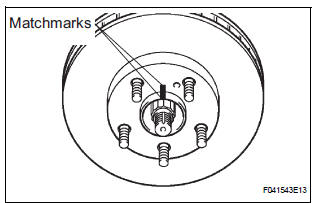
(a) Aligning the matchmarks, install the front disc.
HINT: Select the installation position where the disc has the minimum runout.
2. INSPECT DISC RUNOUT
(a) Temporarily fasten the disc with the hub nuts.
Torque: 103 N*m (1,050 kgf*cm, 76 ft.*lbf)
(b) Using a dial indicator, measure the disc runout 10 mm (0.39 in.) away from the outer edge of the disc.
Maximum disc runout: 0.05 mm (0.0020 in.) (c) If the disc runout is the maximum value or greater, check the bearing play in the axial direction and check for the axle hub runout (See page AH-5). If the bearing play and axle hub runout are normal, adjust the disc runout or grind it on a "On-car" brake lathe.
3. TEMPORARILY TIGHTEN FRONT DISC BRAKE BLEEDER PLUG
(a) Temporarily install the front disc brake bleeder plug to the front disc brake cylinder sub-assembly.
4. INSTALL FRONT DISC BRAKE BLEEDER PLUG CAP
5. INSTALL PISTON SEAL
(a) Apply lithium soap base glycol grease to a new piston seal.
(b) Install the piston seal to the front disc brake cylinder sub-assembly.
6. INSTALL FRONT DISC BRAKE PISTON
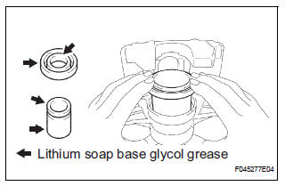
(a) Apply lithium soap base glycol grease to the front disc brake piston and new cylinder boot.
(b) Install the cylinder boot to the front disc brake piston.
(c) Install the front disc brake piston to the front disc brake cylinder sub-assembly.
NOTICE: Do not install the piston forcibly in the front disc brake cylinder sub-assembly.
7. INSTALL CYLINDER BOOT
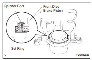
(a) Install a new cylinder boot to the front disc brake cylinder sub-assembly.
NOTICE: Install the boot securely to the grooves of the cylinder and piston.
(b) Using a screwdriver, install the set ring.
NOTICE: Do not damage the cylinder boot.
8. INSTALL FRONT DISC BRAKE BUSH DUST BOOT
(a) Using soft jaws on the vise, hold the front disc brake cylinder mounting LH in the vise through aluminum plates.
(b) Place front disc brake cylinder mounting LH in vise.
(c) Apply lithium soap base glycol grease to the sealing surface of 2 new front disc brake bush dust boots.
(d) Using a socket wrench (19 mm) and hammer, drive the 2 front disc brake bush dust boots to the front disc brake cylinder mounting LH.
 Inspection
1. INSPECT BRAKE CYLINDER AND PISTON
(a) Check the brake cylinder bore and front disc brake
piston for rust or scoring.
2. INSPECT PAD LINING THICKNESS
(a) Using a ruler, measure the pad linin ...
 Installation
HINT:
Install the RH side by the same procedure as the LH side.
1. INSTALL FRONT DISC BRAKE CYLINDER SLIDE BUSH
(a) Apply the lithium soap base glycol grease to a new
front disc brake cylinder ...
Other materials:
On-vehicle inspection
1. INSPECT CENTER AIRBAG SENSOR ASSEMBLY
(VEHICLE NOT INVOLVED IN COLLISION)
Perform a diagnosis system check.
2. INSPECT CENTER AIRBAG SENSOR ASSEMBLY
(VEHICLE INVOLVED IN COLLISION AND AIRBAG
HAS NOT DEPLOYED)
Perform a diagnosis system check.
3. INSPECT CENTER AIRBAG ...
Detailed Bluetooth®
system settings
You can confirm and change the detailed Bluetooth® settings.
How to check and change detailed Bluetooth® settings
Display the “Bluetooth* Setup” screen.
Select “System Settings”.
The following screen is displayed:
Bluetooth* Power on/off
You can change Bluetooth*
fu ...
Voice Recognition Difficulty
INSPECTION PROCEDURE
1 CHECK CONDITION
Check if the system's voice recognition level is low by
using only one particular voice.
OK:
System's voice recognition level is low with any
voice.
2 CHECK MAP DISC
Check that the map disc is not deformed or cracked.
OK:
No deformation ...
