Toyota Sienna Service Manual: Installation
1. INSTALL RACK & PINION POWER STEERING GEAR ASSEMBLY
(a) Install the power steering gear assembly with the 2 bolts and nuts.
Torque: 70 N*m (714 kgf*cm, 52 ft.*lbf)
2. CONNECT PRESSURE FEED TUBE ASSEMBLY
(a) Connect the pressure feed tube assembly to the power steering gear assembly.
(b) Install the clip.
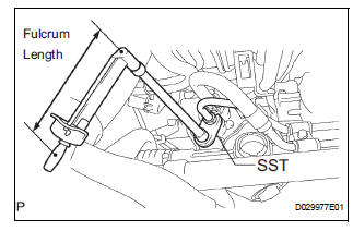
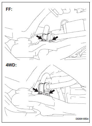
(c) Using SST, connect the return tube assembly to the power steering gear assembly.
SST 09023-12701 Torque: 22.5 N*m (229 kgf*cm, 17 ft.*lbf)
HINT
- Use a torque wrench with a fulcrum length of 300 mm (11.81 in.).
- This torque value is effective when SST is parallel to the torque wrench.
(d) Install the tube clamp with the bolt.
Torque: 9.8 N*m (100 kgf*cm, 87 in.*lbf)
(e) Install the tube clamp with the nut.
Torque: 9.8 N*m (100 kgf*cm, 87 in.*lbf)
3. INSTALL FRONT STABILIZER BRACKET NO.1 LH
(a) Install the stabilizer bracket No. 1 with the 2 bolts.
Torque: 17 N*m (173 kgf*cm, 12 ft.*lbf)
4. INSTALL FRONT STABILIZER BRACKET NO.1 RH
HINT: Perform the same procedure on the other side.
5. INSTALL FRONT STABILIZER LINK ASSEMBLY LH
6. INSTALL FRONT STABILIZER LINK ASSEMBLY RH
HINT: Perform the same procedure on the other side.
7. INSTALL STEERING INTERMEDIATE SHAFT ASSEMBLY
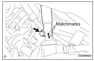
(a) Align matchmarks on the intermediate shaft assembly and power steering gear assembly.
(b) Install the bolt.
Torque: 36 N*m (367 kgf*cm, 27 ft.*lbf)
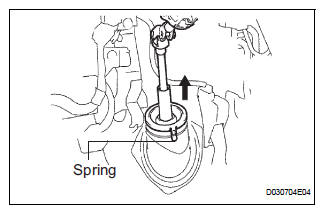
(c) Install the dust cover.
HINT: Ensure that the springs are installed tightly.
8. INSTALL TIE ROD ASSEMBLY LH
9. INSTALL TIE ROD ASSEMBLY RH
HINT: Perform the same procedure on the other side.
10. INSTALL FRONT WHEEL Torque: 103 N*m (1,050 kgf*cm, 76 ft.*lbf)
11. INSPECT CENTER FRONT WHEEL
12. INSPECT STEERING WHEEL CENTER POINT
13. ADD POWER STEERING FLUID
14. BLEED POWER STEERING FLUID
HINT: (See page PS-6)
15. INSPECT FOR POWER STEERING FLUID LEAK
16. INSPECT AND ADJUST FRONT WHEEL ALIGNMENT
HINT: (See page SP-4)
 Reassembly
1. INSTALL RACK STEERING PISTON RING
(a) Coat a new O-ring with power steering fluid and
install it onto the power steering rack.
(b) Expand a new rack steering piston ring with your
fingers ...
 Air conditioning
...
Other materials:
Replying to a message
Display the message inbox screen.
Select the desired message from the list.
Select “Quick Message”.
Select the desired message.
Select “Send”.
If an error message is displayed, follow the guidance on the screen to try
again.
Editing quick reply message
Select “Quick ...
Light Sensor Circuit Malfunction
DTC B1244 Light Sensor Circuit Malfunction
DESCRIPTION
This DTC is output when failure in the light sensor circuit is detected.
DTC No.
DTC Detection Condition
Trouble Area
B1244
Malfunction of automatic light control sensor
Open or short of a ...
Installation
1. INSTALL FRONT STABILIZER BAR
2. INSTALL NO. 1 FRONT STABILIZER BAR BUSHING
(a) Install the 2 front stabilizer bar bush No.1 to the
stabilizer bar front.
NOTICE:
Install the bushings with the slit facing on the
rear side of the vehicle.
HINT:
Install the bushing to the outer side of th ...
