Toyota Sienna Service Manual: Sensor signal check by test mode (signal check) (when using sst check wire)
(a) When having replaced the skid control ECU and/or yaw rate and deceleration sensor, perform zero point calibration of the yaw rate and deceleration sensor.
HINT:
- If the ignition switch is turned from the ON position to the ACC or off during test mode (signal check), DTCs of the signal check function will be erased.
- During test mode (signal check), the skid control ECU records all DTCs of the signal check function. By performing the test mode (signal check), the codes are erased if normality is confirmed. The remaining codes are the codes where an abnormality was found.
(b) Procedures for test mode.
(1) Turn the ignition switch off.
(2) Check that the steering wheel is in the straightahead position and move the shift lever to the P position.
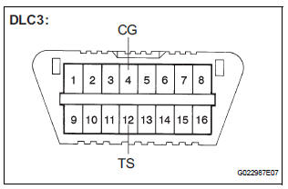
(3) Using SST, connect terminals TS and CG of the DLC3.
SST 09843-18040
(4) Turn the ignition switch to the ON position.
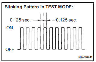
(5) Check that the ABS warning light and VSC warning light blink (test mode).
HINT:
If the ABS warning light and VSC warning light
do not blink, inspect the TS and CG terminal
circuit, ABS warning light circuit and/or VSC
warning light circuit.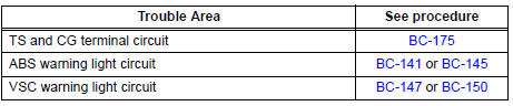
 Yaw rate sensor check (when using intelligent tester)
(a) Check the output of the yaw rate sensor.
(1) Move the shift lever to the D position, drive the
vehicle at a speed of approximately 5 km/h (3
mph), and turn the steering wheel either to th ...
 Master cylinder pressure sensor check (when using sst check wire)
(a) Leave the vehicle in a stationary condition and
release the brake pedal for 1 second or more, and
quickly depress the brake pedal with a force of 98 N
(10 kgf, 22 lbf) or more for 1 second or m ...
Other materials:
Short to B+ in Rear Curtain Shield Squib LH
Circuit
DTC B1638/86 Short to B+ in Rear Curtain Shield Squib LH
Circuit
DESCRIPTION
The rear curtain shield squib LH circuit consists of the center airbag sensor
assembly and the curtain
shield airbag assembly LH.
The circuit instructs the SRS to deploy when deployment conditions are met.
DTC B ...
Removal
HINT:
Use the same procedures for the RH side and LH side.
The procedures listed below are for the LH side.
1. PRECAUTION
CAUTION:
Be sure to read "PRECAUTION" thoroughly before
servicing.
2. DISCONNECT CABLE FROM NEGATIVE BATTERY
TERMINAL
CAUTION:
Wait for 90 s ...
Throttle / Pedal Position Sensor/ Switch
DTC P2120 Throttle / Pedal Position Sensor / Switch "D"
Circuit
DTC P2122 Throttle / Pedal Position Sensor / Switch "D"
Circuit Low Input
DTC P2123 Throttle / Pedal Position Sensor / Switch "D"
Circuit High Input
DTC P2125 Throttle / Pedal Position Sensor / Switch ...
