Toyota Sienna Service Manual: Installation
1. INSTALL BLOWER ASSEMBLY
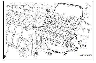
(a) Install the blower assembly.
(b) Install the bolt, the 2 screws and the nut.
Torque: Bolt A 9.8 N*m (100 kgf*cm, 87 in.*lbf)
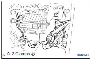
(c) Install the 2 clamps and 2 nuts and wire harness.
2. INSTALL INSTRUMENT PANEL SUB-ASSEMBLY WITH PASSENGER AIRBAG ASSEMBLY
HINT: See page IP-14.
 Reassembly
1. INSTALL BLOWER WITH FAN MOTOR SUBASSEMBLY
2. INSTALL BLOWER MOTOR CONTROL (for
Automatic Air Conditioning System)
3. INSTALL BLOWER RESISTOR (for Manual Air
Conditioning System)
4. INSTALL COO ...
 Blower unit (for rear air conditioning system)
COMPONENTS
...
Other materials:
Correct use of the seat belts
Make sure that all occupants are wearing their seat belts before driving
the vehicle. Use a child restraint system appropriate for the child until the child
becomes large enough to properly wear the vehicle’s seat belt.
Adjusting the mirrors
Make sure that you can see backward clearly by adjus ...
Short in Driver Side Squib 2nd Step Circuit
DTC B1180/17 Short in Driver Side Squib 2nd Step Circuit
DESCRIPTION
The driver side squib 2nd step circuit consists of the center airbag sensor
assembly, the spiral cable and
the steering pad.
The circuit instructs the SRS to deploy when deployment conditions are met.
DTC B1180/17 is rec ...
Front passenger side power
window switch
Inspection
1. INSPECT POWER WINDOW REGULATOR SWITCH ASSEMBLY
Check the resistance between the switch terminals
when the switch is operated.
Standard
If the result is not as specified, replace the switch
assembly. ...
