Toyota Sienna Service Manual: Installation
1. Install thermostat
(a) Install a new gasket to the thermostat.
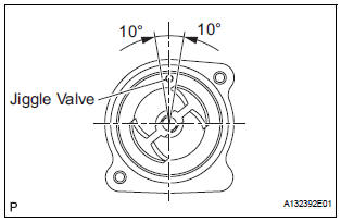
(b) Install the thermostat with the jiggle valve facing up.
Hint: the jiggle valve may be set within 10° on either side of the prescribed position.
2. INSTALL WATER INLET
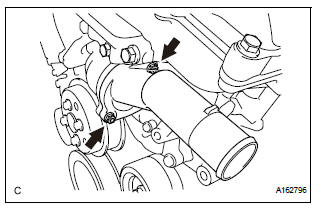
(a) Install the water inlet with the 2 nuts .
Torque: 10 N*m (102 kgf*cm, 7 ft.*lbf)
3. INSTALL NO. 2 IDLER PULLEY SUB-ASSEMBLY
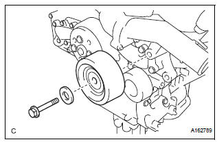
(a) Install the idler pulley cover plate and idler pulley sub-assembly with the bolt.
Torque: 43 N*m (438 kgf*cm, 32 ft.*lbf)
4. CONNECT NO. 2 RADIATOR HOSE
(a) Connect the No. 2 radiator hose to the engine.
5. INSTALL V-RIBBED BELT (See page EM-7) 6. INSTALL FRONT FENDER APRON SEAL RH 7. INSTALL FRONT WHEEL RH 8. ADD ENGINE COOLANT (See page CO-7) 9. INSTALL NO. 1 ENGINE UNDER COVER (See page EM-63) 10. INSPECT FOR COOLANT LEAK (See page CO-1) 11. INSTALL V-BANK COVER SUB-ASSEMBLY (See page EM-63)
 Inspection
1. INSPECT THERMOSTAT
(a) Inspect the thermostat.
HINT:
The valve opening temperature is inscribed on the
thermostat.
(b) Immerse the thermostat in water and gradually heat
the water.
...
 Cooling fan motor
On-vehicle inspection
1. No. 1 Cooling fan motor
(A) check that the motor turns smoothly when the
battery is connected to the fan motor connector.
(B) measure the current while the motor is ...
Other materials:
Rear ceiling lights
Turns the lights on/off
When the personal/interior light
main switch is in the off position,
the rear ceiling lights will not turn
on even if the switch is on.
Adjusting the rear personal/interior lights angle (if equipped)
Push the edge of the light lens.
Illuminated entry system
...
Removal
1. REMOVE ENGINE ASSEMBLY WITH TRANSAXLE
HINT:
See page EM-26
2. REMOVE OIL LEVEL GAUGE GUIDE SUBASSEMBLY
(See page EM-39)
3. REMOVE NO. 1 OIL PIPE (See page EM-77)
4. REMOVE OIL PIPE (See page EM-77)
5. REMOVE CRANKSHAFT PULLEY (See page EM-79)
6. SEPARATE OIL COOLER PIPE
(a) Remove th ...
Personal light assembly
ON-VEHICLE INSPECTION
1. ROOF CONSOLE BOX ASSEMBLY
Inspect map light assembly resistance.
Check the resistance between the terminals at
each switch position as shown in the chart.
Resistance
...
