Toyota Sienna Service Manual: Removal
1. REMOVE ENGINE ASSEMBLY WITH TRANSAXLE
HINT: See page EM-26
2. SECURE ENGINE (See page EM-37) 3. REMOVE GENERATOR ASSEMBLY (See page CH-17) 4. REMOVE COMPRESSOR AND MAGNETIC CLUTCH (See page AC-227) 5. REMOVE NO. 1 ENGINE FRONT MOUNTING BRACKET LH (See page EM-42) 6. REMOVE NO. 2 IDLER PULLEY SUB-ASSEMBLY
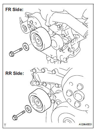
(a) Remove the 2 bolts, 2 idler pulley cover plates and 2 idler pulley sub-assemblies.
7. REMOVE V-RIBBED BELT TENSIONER ASSEMBLY
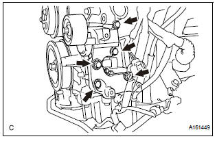
(a) Remove the 5 bolts and V-ribbed belt tensioner assembly.
8. REMOVE WATER PUMP PULLEY
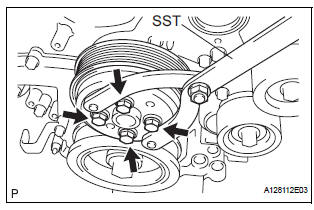
(a) Using SST, hold the water pump pulley.
SST 09960-10010 (09962-01000, 09963-00700) (b) Remove the 4 bolts and water pump pulley.
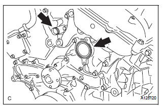
9. REMOVE WATER INLET HOUSING
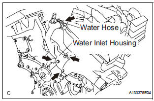
(a) Disconnect the water hose.
(b) Remove the 2 bolts, nut and water inlet housing.
(c) Remove the water inlet housing gasket and water outlet pipe O-ring.
10. REMOVE WATER PUMP ASSEMBLY
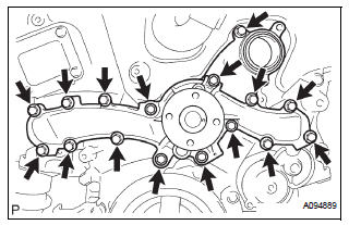
(a) Remove the 16 bolts, water pump assembly and water pump gasket.
 Water pump
COMPONENTS
...
 Inspection
1. Inspect water pump assembly
(a) Visually check the drain hole and air hole for coolant
leakage.
(b) Turn the pulley, and check that the water pump
bearing moves smoothly and noiselessly.
...
Other materials:
Replacement
1. REPLACE GENERATOR DRIVE END FRAME BEARING
(a) Remove the 4 screws and retainer plate from the
drive end frame.
(b) Using SST and a hammer, tap out the drive end
frame bearing from the drive end frame.
SST 09950-60010 (09951-00250), 09950-70010
(09951-07100)
(c) Using SST and a ...
Open in Front Pretensioner Squib LH Circuit
DTC B0136/74 Open in Front Pretensioner Squib LH Circuit
DESCRIPTION
The front pretensioner squib LH circuit consists of the center airbag sensor
assembly and the front seat
outer belt assembly LH.
This circuit instructs the SRS to deploy when deployment conditions are met.
DTC B0136/74 i ...
Data list / active test
1. DATA LIST
(a) While the intelligent tester is connected to the DLC3
with the ignition switch in the ON position, the ABS
data list can be displayed. Follow the prompts on
the tester screen to access the DATA LIST.
2. ACTIVE TEST
HINT:
Performing the ACTIVE TEST using the intelligent te ...
