Toyota Sienna Service Manual: Coolant Thermostat (Coolant Temperature Below Thermostat Regulating Temperature)

HINT:
This DTC relates to the thermostat.
DESCRIPTION
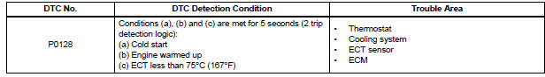
This DTC is set when the Engine Coolant Temperature (ECT) does not reach 75°C (167°F) despite sufficient engine warm-up time.
MONITOR DESCRIPTION
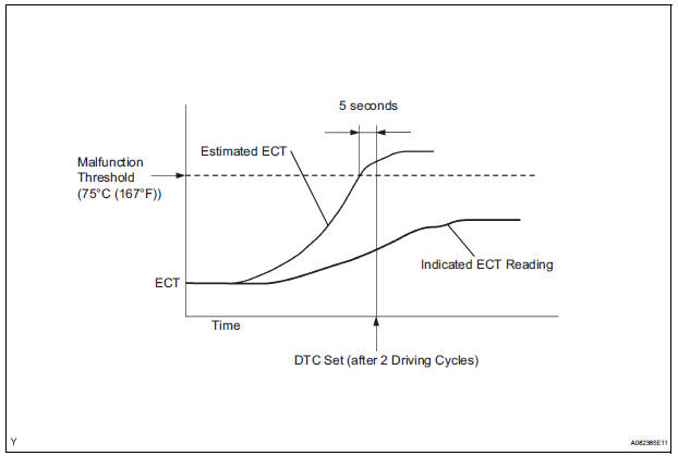
The ECM estimates the ECT based on the starting temperature, engine loads, and engine speeds. The ECM then compares the estimated temperature with the actual ECT. When the estimated ECT reaches 75°C (167°F), the ECM checks the actual ECT. If the actual ECT is less than 75°C (167°F), the ECM interprets this as a malfunction in the thermostat or the engine cooling system and sets the DTC.
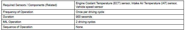
MONITOR STRATEGY

TYPICAL ENABLING CONDITIONS
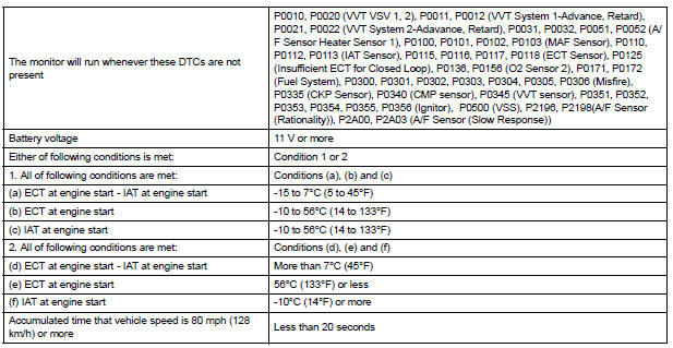
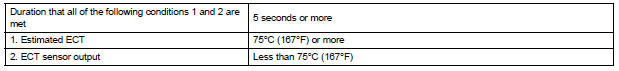
TYPICAL MALFUNCTION THRESHOLDS
INSPECTION PROCEDURE
HINT:
Read freeze frame data using the intelligent tester. The ECM records vehicle and driving condition information as freeze frame data the moment a DTC is stored. When troubleshooting, freeze frame data can be helpful in determining whether the vehicle was running or stopped, whether the engine was warmed up or not, whether the air-fuel ratio was lean or rich, as well as other data recorded at the time of a malfunction.
1 CHECK ANY OTHER DTCS OUTPUT (IN ADDITION TO DTC P0128)
(a) Connect the intelligent tester to the DLC3.
(b) Turn the ignition switch to the ON position.
(c) Turn the tester on.
(d) Select the following menu items: DIAGNOSIS / ENHANCED OBD II / DTC INFO / CURRENT CODES.
(e) Read the DTCs.
Result 
HINT: If any DTCs other than P0128 are output, troubleshoot those DTCs first.


2 CHECK COOLING SYSTEM
(a) Check for defects in the cooling system that might cause the system to be too cold, such as abnormal radiator fan operation or any modifications.

3 INSPECT THERMOSTAT
(a) Remove the thermostat (See page CO-16).
(b) Check the valve opening temperature of the thermostat (See page CO-17).
Standard: 80 to 84°C (176 to 183°F)
HINT:
In addition to the above check, confirm that the valve is completely closed when the temperature is below the standard.
(c) Reinstall the thermostat (See page CO-17).

REPLACE ECM (See page ES-498)
 Insufficient Coolant Temperature for Closed Loop Fuel Control
DESCRIPTION
Refer to DTC P0115 (See page ES-133).
MONITOR DESCRIPTION
The resistance of the ECT sensor varies in proportion to the actual ECT. The
ECM supplies a constant
voltage to the ...
 Oxygen Sensor Circuit
HINT:
Sensor 2 refers to the sensor mounted behind the Three-Way Catalytic
Converter (TWC) and located far
from the engine assembly.
DESCRIPTION
A three-way catalytic converter (TWC) is used ...
Other materials:
Shift Solenoid "D" Performance (Shift Solenoid
Valve S4)
SYSTEM DESCRIPTION
The ECM uses signals from the vehicle speed sensor to detect the actual gear
position (1st, 2nd, 3rd, 4th
or 5th gear).
Then the ECM compares the actual gear with the shift schedule in the ECM memory
to detect mechanical
problems of the shift solenoid valves, valve b ...
Transmitter ID1 Error
DESCRIPTION
The tire pressure warning valve and transmitters that are installed in the
tire and wheel assemblies
measure the air pressure of the tires. The measured values are transmitted to
the tire pressure warning
antenna and receiver on the body as radio waves and then sent to the tir ...
Pressure Control Solenoid "C" Electrical (Shift
Solenoid Valve SL3)
DESCRIPTION
Shifting from 1st to 5th is performed in combination with "ON" and "OFF"
operation of the shift solenoid
valves SL1, SL2, SL3, S4 and SR which are controlled by the ECM. If an open or
short circuit occurs in
either of the shift solenoid valves, the ECM controls ...
