Toyota Sienna Service Manual: Front Speed Sensor RH Circuit
DESCRIPTION
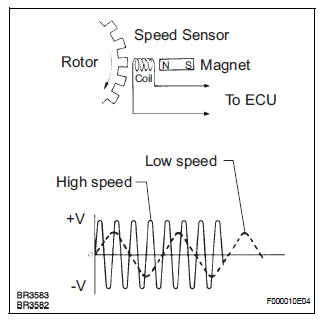
The speed sensor detects wheel speed and transmits the appropriate signals to the ECU. These signals are used for control of the ABS control system. The front and rear rotors have 48 serrations each.
When the rotors rotate, the magnetic field generated by the permanent magnet in the speed sensor induces an AC voltage.
Since the frequency of this AC voltage changes in direct proportion to the speed of the rotor, the frequency is used by the ECU to detect the speed of each wheel.
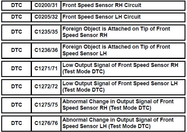
DTCs C1271/71 to C1276/76 can be deleted when the speed sensor sends a vehicle speed signal or the Test Mode ends. DTCs C1271/71 to C1276/76 are output only in the Test Mode.
HINT:
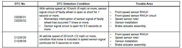
- DTC No. C0200/31 and C1235/35 are for the front speed sensor RH.
- DTC No. C0205/32 and C1236/36 are for the front speed sensor LH.
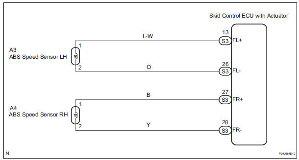
WIRING DIAGRAM
INSPECTION PROCEDURE
HINT: Start the inspection from step 1 when using the intelligent tester and start from step 2 when not using the intelligent tester.
1 READ VALUE OF INTELLIGENT TESTER (FRONT SPEED SENSOR)
(a) Select the DATA LIST mode on the intelligent tester.
ABS: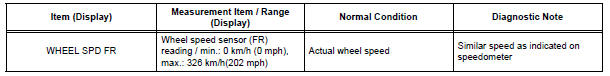
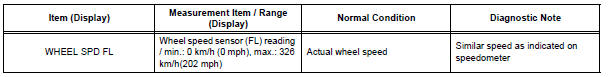
(b) Check that there is the speed value output from the speed sensor displayed on the intelligent tester and the speed value displayed on the speedometer are almost the same when driving the vehicle.
OK: The speed value output from the speed sensor displayed on the intelligent tester is the same as the actual vehicle speed.

2 PERFORM TEST MODE INSPECTION (SIGNAL CHECK)
(a) Clear the DTC (See page BC-10).
(b) Perform sensor signal check in TEST MODE PROCEDURE (See page BC-3).
OK: All Test Mode DTCs are erased.


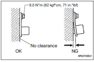
3 INSPECT FRONT SPEED SENSOR INSTALLATION
(a) Turn the ignition switch off.
(b) Check the speed sensor installation.
OK: The installation bolt is tightened properly.
There is no clearance between the sensor and the front steering knuckle.
Torque: 8.0 N*m (82 kgf*cm, 71 in.*lbf)
NOTICE: Check the speed sensor signal after replacement (See page BC-3).

4 INSPECT SPEED SENSOR TIP
(a) Remove the front speed sensor (See page BC-187).
(b) Check the sensor tip.
OK: No scratches or foreign matter on the sensor tip.
NOTICE: Check the speed sensor signal after cleaning or replacement (See page BC-3).

5 INSPECT FRONT SPEED SENSOR
(a) Install the front speed sensor.
(b) Disconnect the front speed sensor connector.
(c) Measure the resistance according to the value(s) in the table below.
Standard resistance:
RH 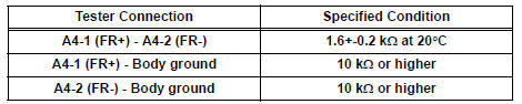
LH 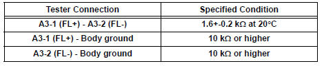
NOTICE: Check the speed sensor signal after replacement (See page BC-3).


6 CHECK HARNESS AND CONNECTOR (BETWEEN SKID CONTROL ECU AND FRONT SPEED SENSOR)
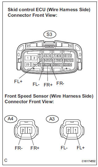
(a) Disconnect the skid control sensor wire.
(b) Measure the resistance according to the value(s) in the table below.
Standard resistance
RH: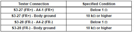
LH: 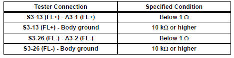

7 INSPECT SPEED SENSOR AND SENSOR ROTOR SERRATIONS
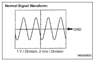
(a) Connect the oscilloscope to terminals FR+ - FR- or FL+ - FL- of the skid control ECU.
(b) Drive the vehicle at about 30 km/h(19 mph), and check the signal waveform.
OK: A waveform as shown in the figure should be output.
HINT:
- As vehicle speed (wheel rotation speed) increases, the width of the waveform narrows and the fluctuation in the output voltage becomes greater.
- When noise is identified in the waveform on the oscilloscope, error signals are generated due to rotor scratches, looseness or foreign matter attached to the speed sensor.

8 RECONFIRM DTC
(a) Clear the DTCs (See page BC-10).
(b) Drive the vehicle at a speed of approximately 32 km/h (20 mph) or more for 60 seconds or more.
(c) Check that the same DTCs are recorded (See page BC- 10).
HINT: Reinstall the sensors, connectors, etc. and restore the vehicle to its prior condition before rechecking for DTCs.
Result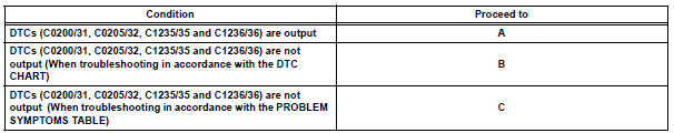

9 INSPECT SPEED SENSOR ROTOR
(a) Turn the ignition switch off.
(b) Remove the front drive shaft (See page DS-5).
(c) Check the rotor.
OK: No scratches, oil, or foreign matter on the rotors.
NOTICE: Check the speed sensor signal after cleaning or replacement (See page BC-3).

REPLACE BRAKE ACTUATOR ASSEMBLY
 Diagnostic trouble code chart
HINT:
If a trouble code is displayed during the DTC check, check
the circuit indicated by the DTC. For details of each code,
turn to the page for the respective DTC Code. in the DTC
chart.
...
 Rear Speed Sensor RH Circuit
DESCRIPTION
Refer to DTCs C0200/31, C0205/32, C1235/35, and C1236/36 (See page BC-17).
DTCs C1273/73 to C1278/78 can be deleted when the speed sensor sends a vehicle
speed signal or the
Tes ...
Other materials:
Control Module Performance
DESCRIPTION
The ECM continuously monitors its main and sub CPUs. This self-check ensures
that the ECM is
functioning properly. If outputs from the CPUs are different and deviate from
the standards, the ECM will
illuminate the MIL and set a DTC immediately.
The ECM also monitors the cru ...
Problem symptoms table
HINT:
Inspect the "Fuse" and "Relay" before confirming the
suspected area as shown in the table below.
DISPLAY FUNCTION:
SOUND FUNCTION:
REMOTE CONTROL FUNCTION:
*1: without Navigation System
*2: with Navigation System ...
Camshaft Position "B" Actuator Circuit
DESCRIPTION
The Variable Valve Timing (VVT) system includes the ECM, OCV and VVT
controller. The ECM sends a
target duty-cycle control signal to the OCV. This control signal regulates the
oil pressure supplied to the
VVT controller. Camshaft timing control is performed according to engine ...
