
Toyota Sienna Service Manual: Installation
HINT:
- Use the same procedures for the RH side and LH side.
- The procedures listed below are for the LH side.
1. INSTALL REAR AIRBAG SENSOR LH
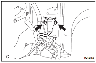
- Check that the ignition switch is off.
- Check that the battery negative (-) terminal is
disconnected.
CAUTION: After disconnecting the negative battery terminal, wait for at least 90 seconds before starting the operation.
- Install the rear airbag sensor LH with the 2 bolts.
Torque: 17.5 N*m (179 kgf*cm, 13 ft.*lbf)
CAUTION:
- If the rear airbag sensor LH has been dropped, or there are any cracks, dents or other defects in the case, bracket or connector, replace it with a new one.
- When installing the rear airbag sensor LH, be careful that the SRS wiring does not interfere with other parts and that it is not pinched between other parts.
- Check that there is no looseness in the installation parts of the rear airbag sensor LH.
- Connect the connector to the rear airbag sensor LH.
2. INSTALL AIR DUCT ASSEMBLY
3. INSTALL FRONT QUARTER TRIM PANEL ASSEMBLY RH
4. INSTALL LAP BELT OUTER ANCHOR COVER
5. INSTALL BACK DOOR SCUFF PLATE
6. INSTALL BACK DOOR WEATHERSTRIP
7. INSTALL REAR DOOR WEATHERSTRIP RH
8. INSTALL REAR DOOR SCUFF PLATE RH
9. CONNECT CABLE TO NEGATIVE BATTERY TERMINAL
10. PERFORM INITIALIZATION
- Perform initialization.
HINT: Some systems need initialization when disconnecting the cable from the negative battery terminal.
11. INSPECT SRS WARNING LIGHT
- Inspect the SRS warning light
 Removal
HINT:
Use the same procedures for the RH side and LH side.
The procedures listed below are for the LH side.
1. PRECAUTION
CAUTION:
Be sure to read "PRECAUTION" thoroug ...
 Seat position sensor
COMPONENTS
...
Other materials:
Reassembly
1. BEARING POSITION
2. INSTALL DIFFERENTIAL GEAR LUBE APPLY TUBE
(a) Install the differential gear lube apply tube and
transaxle apply tube clamp with the bolt to the
transaxle housing.
Torque: 9.8 N*m (100 kgf*cm, 87 in.*lbf)
NOTICE:
Make sure to insert the pipe to the s ...
Removal
1. RECOVER REFRIGERANT FROM REFRIGERATION
SYSTEM (See page AC-172)
2. REMOVE NO. 2 AIR CLEANER INLET (See page EM-
28)
3. REMOVE FRONT BUMPER ASSEMBLY (See page
ET-3)
4. DISCONNECT DISCHARGE HOSE SUB-ASSEMBLY
(a) Remove the bolt and disconnect the discharge hose
sub-assembly from the coo ...
Installation
1. INSTALL BRAKE VACUUM CHECK VALVE
ASSEMBLY
(a) Install the brake vacuum check valve assembly and
check valve grommet to the brake booster
assembly.
2. INSTALL BRAKE BOOSTER GASKET
(a) Install a new brake booster gasket to the brake
booster with master cylinder.
3. INSTALL BRAKE MASTER CYLI ...
