Toyota Sienna Service Manual: Installation
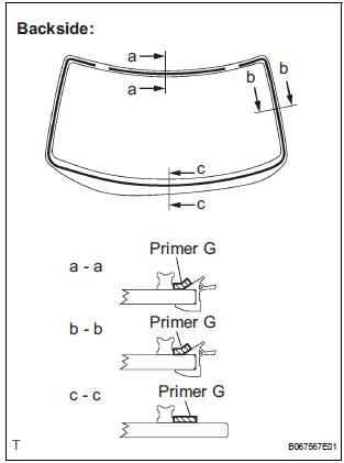
1. INSTALL WINDSHIELD GLASS NO.2 STOPPER
- Coat the installation part of the stoppers with Primer G.
NOTICE:
- Allow the primer coating to dry for 3 minutes or more.
- Do not keep any of the opened Primer G for later use.
- Do not apply too much Primer .
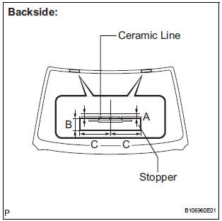
- Install 2 new stoppers onto the glass, as shown in the illustration.
Dimension
2. INSTALL WINDSHIELD GLASS NO.1 STOPPER
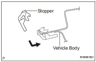
- Install 2 new stoppers to the vehicle body, as shown in the illustration.
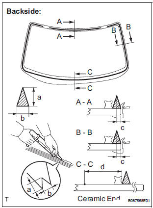
3. INSTALL WINDOW GLASS ADHESIVE DAM
- Coat the installation part of the windshield glass adhesive dam with Primer G.
NOTICE:
- Allow the primer coating to dry for 3 minutes or more.
- Do not apply too much Primer.
- Install a new dam, applying double-sided tape all the way around the glass except where the stoppers are installed, as shown in the illustration
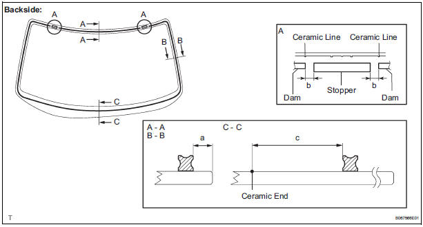
Dimension
4. INSTALL WINDSHIELD MOULDING OUTER UPPER
- Using the brush or sponge, coat the edge of the glass and the contact surface with Primer G.
NOTICE:
- Allow the primer coating to dry for 3 minutes or more.
- Do not coat the adhesive with Primer G.
- Do not keep any of the opened Primer G for later use.
- Install the moulding.
5. INSTALL WINDSHIELD GLASS
- Clean and shape the contact surface of the vehicle body.
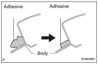
- Using a knife, cut away any rough adhesive on the contact surface of the vehicle body to ensure the appropriate surface shape.
HINT: Leave as much of the adhesive on the vehicle body as possible.
- Clean the contact surface of the vehicle body with a piece of shop rag saturated with cleaner.
HINT: Even if all the adhesive has been removed, clean the vehicle body.
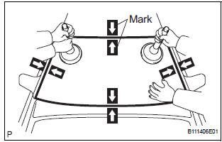
- Position the glass.
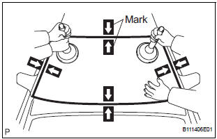
- Using a suction cup, place the glass in the correct position.
- Check that the whole contact surface of the glass rim is perfectly even.
- Place reference marks between the glass and vehicle body.
NOTICE: Check that the stoppers are attached to the vehicle body correctly.
HINT: When reusing the glass, check and correct the reference mark positions.
- Remove the glass.
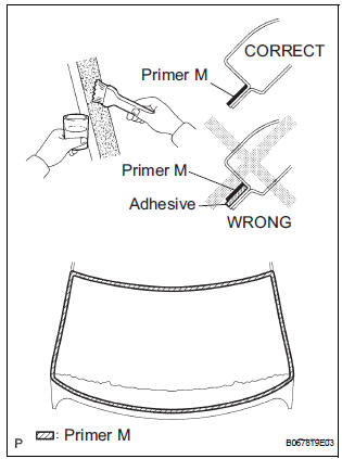
- Using a brush, coat the exposed part of the vehicle body with Primer M.
NOTICE:
- Allow the primer coating to dry for 3 minutes or more.
- Do not coat the adhesive with Primer M.
- Do not keep any of the opened Primer M for later use.
- Using a brush or sponge, coat the edge of the glass and the contact surface with Primer G.
HINT: If the area other than that specified is coated by accident, wipe off the primer with a clean shop rag before it dries.
NOTICE:
- Allow the primer coating to dry for 3 minutes or more.
- Do not keep any of the opened Primer G for later use.
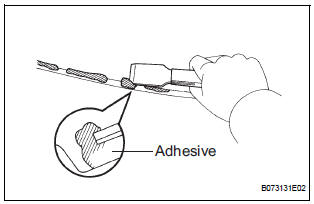
- Apply adhesive (Adhesive: Part No.08850-00801 or equivalent).
- Cut off the tip of the cartridge nozzle, as shown in the illustration.
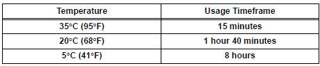
HINT: After cutting off the tip, use all adhesive within the time described in the table below.
Tackfree time
- Load the sealer gun with the cartridge.
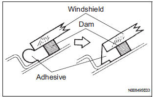
- Coat the glass with adhesive, as shown in the illustration.
Dimension
- Install the glass.
- Using a suction cup, position the glass so that the reference marks are aligned. Press it in gently along the rim.
NOTICE:
- Allow the primer coating to dry for 3 minutes or more.
- Check that the stoppers are attached to the vehicle body correctly.
- Check that clearance between the vehicle body and glass.
- Lightly press the front surface of the glass to ensure a close fit.
- Using a scraper, remove any excess or protruding adhesive.
HINT: Apply adhesive on the glass rim
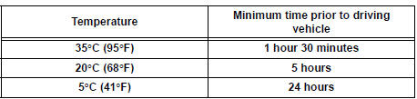
NOTICE: Do not drive the vehicle for the amount of time described in the table below.
Minimum time
6. REMOVE WINDSHIELD MOULDING OUTSIDE LH
7. INSTALL WINDSHIELD MOULDING OUTSIDE RH
8. CHECK FOR LEAKS AND REPAIR
- Conduct a leak test after the adhesive has completely hardened.
- Seal any leaks with auto glass sealer.
9. INSTALL COWL TOP VENTILATOR LOUVER SUBASSEMBLY
10. INSTALL FRONT WIPER ARM RH
11. INSTALL FRONT WIPER ARM LH
12. REMOVE FRONT WIPER ARM HEAD CAP
13. INSTALL ROOF HEADLINING ASSEMBLY
14. INSTALL INNER REAR VIEW MIRROR ASSEMBLY
15. REMOVE SUN ROOF OPENING TRIM MOULDING (W/ SLIDING ROOF)
16. INSTALL ROOF CONSOLE BOX ASSEMBLY
17. INSTALL VISOR HOLDER
18. INSTALL ASSIST GRIP SUB-ASSEMBLY
19. INSTALL VISOR ASSEMBLY RH
20. INSTALL VISOR ASSEMBLY LH
21. INSTALL FRONT PILLAR GARNISH RH
22. INSTALL FRONT PILLAR GARNISH LH
23. INSTALL FRONT DOOR OPENING TRIM WEATHERSTRIP RH
24. INSTALL FRONT DOOR OPENING TRIM WEATHERSTRIP LH
 Removal
1. REMOVE FRONT DOOR OPENING TRIM
WEATHERSTRIP LH
2. REMOVE FRONT DOOR OPENING TRIM
WEATHERSTRIP RH
3. REMOVE FRONT PILLAR GARNISH LH
4. REMOVE FRONT PILLAR GARNISH RH
5. REMOVE VISOR ASSEMBLY L ...
 Rear side window glass
COMPONENTS
...
Other materials:
Television Display Assembly Communication Error
INSPECTION PROCEDURE
1 IDENTIFY THE COMPONENT SHOWN BY THE SUB-CODE
Enter the diagnostic mode.
Press the preset switch "3" to change to "Detailed
Information Mode".
Identify the component shown by the sub-code.
HINT:
"190 (radio receiver)" ...
Data list / active test
1. DATA LIST
HINT:
Using the intelligent tester's DATA LIST allows the status
of a switch, sensor, actuator and other items to be read
without removing any parts. Reading the DATA LIST
early in troubleshooting is one way to save time.
Connect the intelligent tester (with CAN VIM) to t ...
Power Seat Motor Circuit
DESCRIPTION
When the power seat control switch is operated, a command signal is sent to
the position control ECU
and switch assembly (power seat control switch and ECU). The front power seat
switch then controls the
appropriate seat motor as needed. This memory system does not use a seat
po ...
