Toyota Sienna Service Manual: Installation
1. INSTALL INSTRUMENT PANEL SAFETY PAD SUBASSEMBLY
- Using a torque wrench, install the bolt <B>.
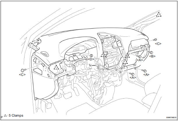
Torque: 20 N*m (204 kgf*cm, 14 ft.*lbf)
2. INSTALL SHIFT LEVER ASSEMBLY
- Using a torque wrench, install the 4 bolts.
Torque: 21 N*m (214 kgf*cm, 12.6 ft.*lbf)
3. INSTALL DEFROSTER NOZZLE OPENING PLATE NO.1
4. INSTALL FRONT NO.2 SPEAKER ASSEMBLY
5. INSTALL FRONT NO.1 SPEAKER ASSEMBLY
6. INSTALL INSTRUMENT PANEL SPEAKER PANEL SUB-ASSEMBLY NO.2
7. INSTALL INSTRUMENT PANEL SPEAKER PANEL SUB-ASSEMBLY
8. INSTALL FRONT PILLAR GARNISH RH
9. INSTALL FRONT PILLAR GARNISH LH
10. INSTALL INTEGRATION CONTROL & PANEL ASSEMBLY
11. INSTALL RADIO RECEIVER ASSEMBLY
12. INSTALL STEREO COMPONENT SPEAKER ASSEMBLY
13. INSTALL INSTRUMENT CLUSTER FINISH PANEL GARNISH
14. INSTALL INSTRUMENT CLUSTER FINISH PANEL SUB-ASSEMBLY LOWER CENTER
15. INSTALL INSTRUMENT CLUSTER FINISH PANEL ASSEMBLY CENTER
16. INSTALL FLOOR SHIFT POSITION INDICATOR HOUSING ASSEMBLY
17. INSTALL SHIFT LEVER KNOB SUB-ASSEMBLY
18. INSTALL INSTRUMENT CLUSTER FINISH PANEL CENTER NO.2
19. INSTALL INSTRUMENT CLUSTER FINISH PANEL CENTER NO.1
20. INSTALL FLOOR CARPET COVER CENTER RH
21. INSTALL FLOOR CARPET COVER CENTER LH
22. INSTALL INSTRUMENT PANEL REGISTER ASSEMBLY NO.3
23. INSTALL INSTRUMENT PANEL REGISTER ASSEMBLY NO.1
24. INSTALL INSTRUMENT SIDE PANEL RH
25. INSTALL INSTRUMENT SIDE PANEL LH
26. INSTALL INSTRUMENT PANEL BOX NO.2
27. INSTALL GLOVE COMPARTMENT DOOR ASSEMBLY
28. INSTALL GLOVE COMPARTMENT DOOR STOPPER SUB-ASSEMBLY
29. INSTALL INSTRUMENT PANEL SAFETY PAD INSERT SUB-ASSEMBLY NO.1
30. INSTALL INSTRUMENT PANEL FINISH PANEL SUBASSEMBLY LOWER LH
31. INSTALL COWL SIDE TRIM BOARD RH
32. INSTALL COWL SIDE TRIM BOARD LH
33. INSTALL FRONT DOOR SCUFF PLATE RH
34. INSTALL FRONT DOOR SCUFF PLATE LH
35. INSTALL COMBINATION METER ASSEMBLY
36. INSTALL INSTRUMENT CLUSTER FINISH PANEL SUB-ASSEMBLY
37. INSTALL WINDSHIELD WIPER SWITCH ASSEMBLY
38. INSTALL HEADLIGHT DIMMER SWITCH ASSEMBLY
39. INSTALL SPIRAL CABLE SUB-ASSEMBLY
40. INSTALL STEERING COLUMN COVER
41. ADJUST SPIRAL CABLE SUB-ASSEMBLY
42. INSTALL STEERING WHEEL ASSEMBLY
43. INSTALL HORN BUTTON ASSEMBLY
44. INSTALL STEERING WHEEL COVER LOWER NO.2
45. INSTALL STEERING WHEEL COVER LOWER NO.3
46. CONNECT BATTERY NEGATIVE TERMINAL
47. INSPECT HORN BUTTON ASSEMBLY
48. INSPECT SRS WARNING LIGHT
 Reassembly
1. INSTALL INSTR PNL PASS L/DOOR AIR BAG
ASSEMBLY
2. INSTALL INSTRUMENT PANEL WIRE NO.2
3. INSTALL NAVIGATION ANTENNA ASSEMBLY
4. INSTALL ANTENNA CORD SUB-ASSEMBLY
5. INSTALL INSTRUMENT PANEL BOX ...
 Seat belt
...
Other materials:
CD Sound Skips
INSPECTION PROCEDURE
1 CHECK CD
Check the CD.
OK:
The CD is clean.
HINT:
If dirt is on the CD surface, wipe it clean with a soft cloth
from the inside to the outside in a radial direction.
NOTICE:
Do not use a conventional record cleaner or antistatic
preservative.
2 CHECK CD
...
Warning lights
Warning lights inform the driver of malfunctions in the indicated vehicle’s
systems.
*1: These lights turn on when the engine switch is turned to the “ON”
position
(vehicles without a smart key system) or IGNITION ON mode (vehicles
with a smart key system) to indicate that a system c ...
On-vehicle inspection
1. CONNECT INTELLIGENT TESTER
(a) Connect the intelligent tester to the DLC3.
(b) Start the engine and run at idle.
(c) Select the ACTIVE TEST mode on the intelligent
tester.
HINT:
Please refer to the intelligent tester operator's
manual for further details.
2. INSPECT ACTUATOR MOTOR ...
