Toyota Sienna Service Manual: Installation
1. INSTALL 3 POINT TYPE NO. 2 REAR SEAT BELT ASSEMBLY
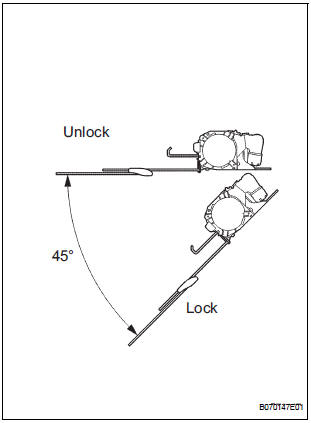
- Check the degree of tilt when the belt begins to lock the ELR.
- Check that the belt does not lock within 15 of
tilt in all directions but that the belt locks with
over 45 of tilt, when gently moving the
retractor.
If operation is not as specified, replace the 3 point type No. 2 rear seat belt assembly.
- Install the 3 point type No. 2 rear seat belt assembly
with the 3 bolts and 2 nuts.
Torque: 42 N*m (430 kgf*cm, 31 ft.*lbf)
- Check the ELR lock.
NOTICE: The check should be performed with the assembly installed.
- Check that the belt locks when pulling out the
belt quickly when the belt is installed.
If operation is not as specified, replace the 3 point type No. 2 rear seat belt assembly.
- Check the fastening function of the child restraint system.
NOTICE: The check should be performed with the assembly installed.
- Check that the belt cannot be pulled out any more but can be rewound after the belt is fully pulled out.
- Check that the belt can be pulled out and
rewound after the belt is fully rewound.
If operation is not as specified, replace the 3 point type No. 2 rear seat belt assembly.
- Install the roof headlining.
HINT: Refer to the instructions for installation of the roof headlining (4).
2. INSTALL NO. 1 REAR SEAT OUTER BELT ASSEMBLY (for 8-Passenger)
HINT: Refer to the instructions for reassembly of the rear No .1 seat assembly (for center seat).
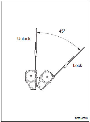
- Check the degree of tilt when the belt begins to lock the ELR.
- Check that the belt does not lock within 15 of
tilt in all directions but that the belt locks with
over 45 of tilt, when gently moving the
retractor.
If operation is not as specified, replace the No.
1 rear seat outer belt assembly.
- Install the No. 1 rear seat outer belt assembly with
the 2 bolts and 2 nuts.
Torque: 42 N*m (430 kgf*cm, 31 ft.*lbf)
- Check the ELR lock.
NOTICE: The check should be performed with the assembly installed.
- Check that the belt locks when pulling out the belt quickly when the belt is installed.
HINT: The seat belt does not lock when the pull out amount of the belt is 955 mm (37.60 in.) or less.
If operation is not as specified, replace the No.
1 rear seat outer belt assembly.
- Check the fastening function of the child restraint system.
NOTICE: The check should be performed with the assembly installed.
- Check that the belt cannot be pulled out any more but can be rewound after it is fully pulled out.
- Check that the belt can be pulled out and
rewound after the belt is fully rewound.
If operation is not as specified, replace the No.
1 rear seat outer belt assembly.
- Install the rear seat shoulder belt cover.
- Install the rear seatback board.
 Removal
1. REMOVE NO. 1 REAR SEAT OUTER BELT
ASSEMBLY (for 8-Passenger)
HINT:
Refer to the instructions for disassembly of the rear No .1
seat assembly (for center seat).
Remove the rear seatback boar ...
 Seat
Seat
...
Other materials:
Open in Side Squib LH Circuit
DTC B0116/48 Open in Side Squib LH Circuit
DESCRIPTION
The side squib LH circuit consists of the center airbag sensor assembly and
the front seat side assembly
LH.
This circuit instructs the SRS to deploy when deployment conditions are met.
DTC B0116/48 is recorded when an open circuit is ...
Sound Signal Circuit between Radio Receiver and Television Display
Assembly
DESCRIPTION
The television display assembly sends a sound signal to the radio receiver
through this circuit.
The sound signal that has been sent is amplified by the stereo component
amplifier or radio receiver
(built-in amplifier), and then is sent to the speakers.
If there is an open or ...
Short to B+ in Driver Side Squib Circuit
DTC B0103/12 Short to B+ in Driver Side Squib Circuit
DESCRIPTION
The driver side squib circuit consists of the center airbag sensor assembly,
the spiral cable and the
steering pad.
The circuit instructs the SRS to deploy when deployment conditions are met.
DTC B0103/12 is recorded when a ...
