Toyota Sienna Service Manual: Installation
1. INSTALL REAR NO. 2 SEAT ASSEMBLY
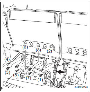
- Lock the seat leg rear to the floor striker.
- Lock the seat leg front to the floor striker.
- Install the rear No. 2 seat assembly with the 8 bolts.
Torque: 19 N*m (194 kgf*cm, 14 ft.*lbf)
NOTICE: Tighten the bolts in the order shown in the illustration.
- Connect the connector.
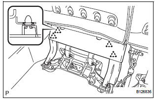
2. INSTALL NO. 2 SEAT HINGE COVER
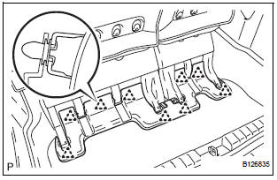
3. INSTALL REAR SEAT LEG SIDE GARNISH SUBASSEMBLY
- Install 4 new clips to the rear seat leg side garnish sub-assembly.
- Engage the 4 clips and install the rear seat leg side garnish sub-assembly.
4. INSTALL REAR NO. 2 SEAT LEG SIDE GARNISH SUB-ASSEMBLY
- Install 9 new clips to the rear No. 2 seat leg side garnish sub-assembly.
- Engage the 4clips and install the rear No. 2 seat leg side garnish sub-assembly.
5. CONNECT CABLE TO NEGATIVE BATTERY TERMINAL
6. CHECK POWER REAR NO. 2 SEAT WITH STOWING FUNCTION
7. PERFORM INITIALIZATION
Some systems need initialization after reconnecting the cable to the negative battery terminal.
 Reassembly
1. INSTALL NO. 2 SEAT LEG SUB-ASSEMBLY
Install the No. 2 seat leg sub-assembly with the 3
bolts and 2 nuts.
Torque: 19 N*m (194 kgf*cm, 14 ft.*lbf)
NOTICE:
Tighten the bolts and ...
 Rear no. 2 Seat assembly (for Power Seat Type RH Side)
COMPONENTS
...
Other materials:
Installation
1. INSTALL IGNITION SWITCH ASSEMBLY
(a) Install the ignition switch with the 2 screws.
(b) Install the ignition switch connector.
2. INSTALL STEERING COLUMN COVER LOWER
(a) Attach the 4 claws to install the steering column
cover lower.
(b) Insert the key into the ignition key cylinde ...
Adjustment
1. VEHICLE PREPARATION FOR HEADLIGHT AIMING
ADJUSTMENT
Prepare the vehicle:
Ensure there is no damage or deformation to the
body around the headlights.
Fill the fuel tank.
Make sure that the oil is filled to the specified
level.
Make sure that the c ...
Stowing the third seats (manual seats)
Before stowing or returning third seat, remove any items from the floor
area to prevent interference with moving parts.
Before stowing the third seats
Lower the center head
restraint to the lowest position
, and stow the
seat belt buckles.
Stow the center seat belt.
Stowing ...
