Toyota Sienna Service Manual: Reassembly
1. INSTALL NO. 2 SEAT LEG SUB-ASSEMBLY
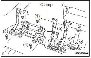
- Install the No. 2 seat leg sub-assembly with the 3
bolts and 2 nuts.
Torque: 19 N*m (194 kgf*cm, 14 ft.*lbf) NOTICE: Tighten the bolts and nuts in the order shown in the illustration.
- Install the 3 clamps.
2. INSTALL NO. 2 SEAT CUSHION FRAME SUBASSEMBLY
3. INSTALL NO. 2 SEAT CUSHION SPRING ASSEMBLY
4. INSTALL NO. 2 SEAT CUSHION STOPPER
5. INSTALL REAR SEAT WIRE
6. INSTALL NO. 2 SEAT CUSHION PAD
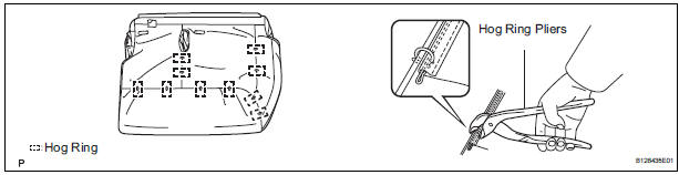
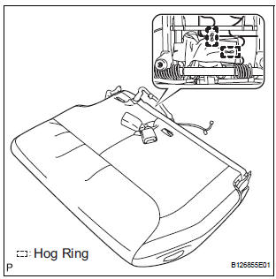
7. INSTALL NO. 2 SEAT CUSHION COVER SUBASSEMBLY
- Using hog ring pliers, install the No. 2 seat cushion cover sub-assembly to the No. 2 seat cushion pad with 10 new hog rings.
NOTICE:
- Be careful not to damage the cover.
- When installing the hog rings, take care to minimize wrinkles as much as possible.
8. INSTALL NO. 2 SEAT CUSHION COVER SUBASSEMBLY WITH PAD
9. INSTALL REAR SEAT COVER
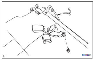
10. INSTALL REAR SEAT BELT ASSEMBLY INNER
- Install the rear seat belt assembly inner with the
bolt.
Torque: 44 N*m (449 kgf*cm, 33 ft.*lbf)
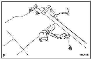
11. INSTALL REAR NO. 2 SEAT BELT ASSEMBLY INNER
- Install the rear No. 2 seat belt assembly inner with
the bolt.
Torque: 44 N*m (449 kgf*cm, 33 ft.*lbf)
- Using hog ring pliers, install 2 new hog rings.
NOTICE: Be careful not to damage the cover.
12. INSTALL REAR NO. 2 SEAT LAP BELT ASSEMBLY CENTER WITH INNER
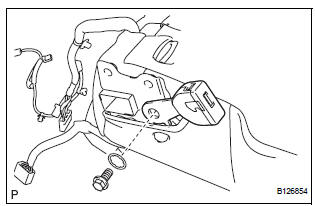
- Install the rear No. 2 seat lap belt assembly center
with inner with the bolt and washer.
Torque: 44 N*m (449 kgf*cm, 33 ft.*lbf)
13. INSTALL REAR POWER SEAT SWITCH
14. INSTALL RECLINING REMOTE CONTROL LEVER BEZEL
15. INSTALL NO. 2 SEATBACK FRAME SUB-ASSEMBLY
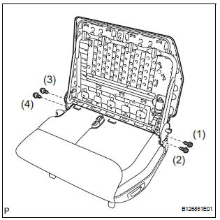
- Install the No. 2 seatback frame sub-assembly with
the 4 bolts.
Torque: 44 N*m (449 kgf*cm, 33 ft.*lbf)
NOTICE:
- Tighten the bolts in the following order:
- Temporarily tighten bolt (1).
- Temporarily tighten bolt (2).
- Fully tighten bolt (3).
- Fully tighten bolt (4).
- Fully tighten bolt (1).
- Fully tighten bolt (2).
16. INSTALL FOLD SEAT CONTROL ECU
17. INSTALL NO. 2 SEATBACK PAD
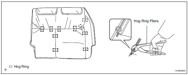
18. INSTALL NO. 2 SEATBACK COVER SUB-ASSEMBLY
- Using hog ring pliers, install the No. 2 seatback cover sub-assembly to the No. 2 seatback pad with 10 new hog rings.
NOTICE:
- Be careful not to damage the cover.
- When installing the hog rings, take care to minimize wrinkles as much as possible.
19. INSTALL NO. 2 SEATBACK COVER SUB-ASSEMBLY WITH PAD
20. INSTALL REAR NO. 2 SEAT HEADREST SUPPORT ASSEMBLY RH
21. INSTALL REAR NO. 2 SEAT HEADREST SUPPORT ASSEMBLY LH
22. INSTALL REAR SEAT HEADREST ASSEMBLY
23. INSTALL REAR SEAT RECLINING COVER RH
24. INSTALL REAR SEAT RECLINING COVER LH
25. INSTALL REAR NO. 2 SEAT COVER BEZEL
 Adjustment
HINT:
If the malfunction does not disappear by following the
procedure in ADJUSTMENT and the rear No. 2 seat
assembly needs to be replaced, do not disassemble the rear
No. 2 seat assembly.
1. ADJ ...
 Installation
1. INSTALL REAR NO. 2 SEAT ASSEMBLY
Lock the seat leg rear to the floor striker.
Lock the seat leg front to the floor striker.
Install the rear No. 2 seat assembly with t ...
Other materials:
Casual speech recognization
Due to natural language speech recognition technology, this system
enables recognition of a command when spoken naturally. However,
the system cannot recognize every variation of each command.
In some situations, it is possible to omit the command for the procedure
and directly state the desir ...
Inspection
1. INSPECT PARK/NEUTRAL POSITION SWITCH ASSEMBLY OPERATION
(a) Apply the parking brake and turn the ignition switch
to the ON position.
(b) Depress the brake pedal and check that the engine
starts only when the shift lever is in the N or P
position and the engine does not start when the shift ...
Hood
COMPONENTS
Adjustment
HINT:
Since a centering bolt is used as a hood hinge mounting bolt
and hood lock mounting bolt, the hood and hood lock can not
be adjusted with them on. Substitute a bolt with a washer for
the centering bolt.
1. INSPECT HOOD SUB-ASSEMBLY
Check that the clearance is ...
