Toyota Sienna Service Manual: Installation
1. INSTALL REAR NO. 2 SEAT ASSEMBLY
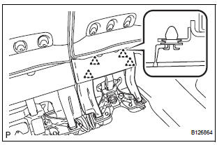
- Lock the seat leg rear to the floor striker.
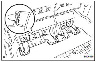
- Lock the seat leg front to the floor striker.
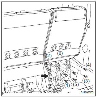
- Install the rear No. 2 seat assembly with the 6 bolts.
Torque: 19 N*m (194 kgf*cm, 14 ft.*lbf)
NOTICE: Tighten the bolts in the order shown in the illustration.
- Connect the connector.
2. INSTALL NO. 2 SEAT HINGE COVER
3. INSTALL REAR SEAT LEG SIDE GARNISH SUBASSEMBLY
- Install 4 new clips to the rear seat leg side garnish sub-assembly.
- Engage the 4 clips and install the rear seat leg side garnish sub-assembly.
4. INSTALL REAR NO. 2 SEAT LEG SIDE GARNISH SUB-ASSEMBLY
- Install 9 new clips to the rear No. 2 seat leg side garnish sub-assembly.
- Engage the 4 clips and install the rear No. 2 seat leg side garnish sub-assembly.
5. CONNECT CABLE TO NEGATIVE BATTERY TERMINAL
6. CHECK POWER REAR NO. 2 SEAT WITH STOWING FUNCTION
7. PERFORM INITIALIZATION
Some systems need initialization after reconnecting the cable to the negative battery terminal.
 Reassembly
1. INSTALL NO. 2 SEAT LEG SUB-ASSEMBLY
Install the No. 2 seat leg sub-assembly with the 3
bolts and nut.
Torque: 19 N*m (194 kgf*cm, 14 ft.*lbf)
NOTICE:
Tighten the bolts and nut ...

Other materials:
Fastening the seat belt (for the third center seat)
Take the plate out of the holder,
and then pull down the seat
belt.
Push plate “A” into buckle “A”
until a click sound is heard.
Push plate “B” into buckle “B”
until a click sound is heard.
...
System description
1. SYSTEM DESCRIPTION
(a) ABS
(Anti-lock Brake System)
The ABS helps prevent wheels from locking when
the brake is applied firmly or when braking on a
slippery surface.
(b) EBD
(Electronic Brake force Distribution)
The EBD control utilizes ABS, realizing proper
brake force distribution betw ...
Inspection
1. Inspect starter assembly
NOTICE:
These tests must be performed within 3 to 5 seconds
to avoid burning out the coil.
(a) Perform the pull-in test.
(1) Disconnect the lead wire from terminal C.
(2) Connect the battery to the magnetic switch as
shown in the illustratio ...
