Toyota Sienna Service Manual: Installation
1. INSTALL PARK/NEUTRAL POSITION SWITCH ASSEMBLY
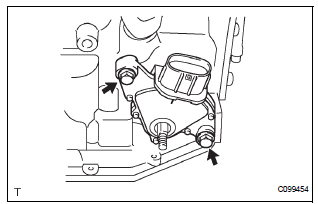
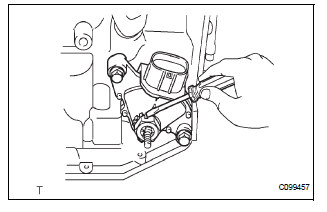
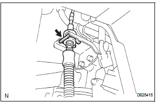
(a) Install the park/neutral position switch to the manual valve shaft.
(b) Temporarily install the 2 bolts.
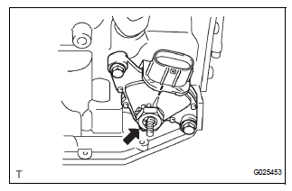
(c) Place a new lock plate and tighten the nut.
Torque: 6.9 N*m (70 kgf*cm, 61 in.*lbf) (d) Temporarily install the control shaft lever.
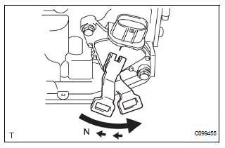
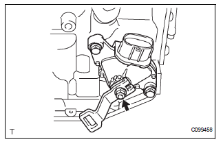
(e) Turn the lever counterclockwise until it stops, then turn it clockwise 2 notches.
(f) Remove the control shaft lever.
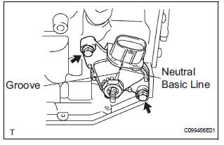
(g) Align the groove with the neutral basic line.
(h) Hold the switch in position and tighten the 2 bolts.
Torque: 5.4 N*m (55 kgf*cm, 48 in.*lbf)
(i) Using a screwdriver, bend the tabs of the lock plate.
(j) Install the control shaft lever, washer and the nut.
Torque: 13 N*m (130 kgf*cm, 9 ft.*lbf)
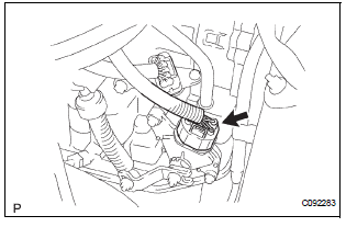
(k) Connect the park/neutral position switch connector
2. CONNECT TRANSMISSION CONTROL CABLE ASSEMBLY
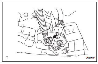
(a) Connect the control cable to the control shaft lever with the nut.
Torque: 13 N*m (133 kgf*cm, 10 ft.*lbf)
(b) Install the control cable with a new clip to the bracket.
3. ADJUST PARK/NEUTRAL POSITION SWITCH ASSEMBLY (See page AX-127)
4. INSPECT PARK/NEUTRAL POSITION SWITCH ASSEMBLY OPERATION (See page AX-126)
5. INSPECT SHIFT LEVER POSITION (See page AX-148)
6. ADJUST SHIFT LEVER POSITION (See page AX-149)
7. INSTALL AIR CLEANER ASSEMBLY
HINT: (See page EM-44)
8. INSTALL BATTERY
 Inspection
1. INSPECT PARK/NEUTRAL POSITION SWITCH ASSEMBLY OPERATION
(a) Apply the parking brake and turn the ignition switch
to the ON position.
(b) Depress the brake pedal and check that the engine
star ...
Other materials:
DVD-ROM Abnormal
DTC 44-43 DVD-ROM Abnormal
DESCRIPTION
DTC No.
DTC Detecting Condition
Trouble Area
44-43
DVD-ROM operation is abnormal.
DVD
Television display assembly
INSPECTION PROCEDURE
HINT:
After the inspection is completed, clear the ...
Checking monitor status
The purpose of the monitor result (mode 06) is to allow
access to the results for on-board diagnostic monitoring tests
of specific components/systems that are not continuously
monitored. Examples are catalyst, evaporative emission
(EVAP) and thermostat.
The monitor result allows the OBD II sc ...
Diagnostic trouble code chart
If a trouble code is displayed during the DTCs check (sensor
check), check the circuit listed for the code in the table below
(Proceed to the page given for that circuit).
AIR CONDITIONING SYSTEM
HINT:
*1: If the cabin temperature is approximately -18.6°C (-
3.7°F) or lo ...
