Toyota Sienna Service Manual: Installation
1. INSTALL SLIDE DOOR ROLLER ASSEMBLY UPPER
- Apply MP grease to the rotating area of the roller.
- Install the roller with the 2 bolts.
Torque: 13 N*m (130 kgf*cm, 10 ft.*lbf)
2. INSTALL SLIDE DOOR HINGE ASSEMBLY CENTER LH
- Apply MP grease to the rotating areas of the hinge.
- Install the hinge with the 3 bolts.
Torque: 31 N*m (316 kgf*cm, 23 ft.*lbf)
3. INSTALL SLIDE DOOR ROLLER ASSEMBLY LOWER LH
- Apply MP grease to the rotating area of the roller.
- Install the roller with the 3 bolts.
Torque: 31 N*m (316 kgf*cm, 23 ft.*lbf)
4. INSTALL SLIDE DOOR FULL OPEN STOP LOCK ASSEMBLY LH

- Apply MP grease to the sliding and rotating areas of the lock.
- Install the lock with the 2 bolts.
Torque: 8.0 N*m (82 kgf*cm, 71 in.*lbf)
- Install the 2 cables.
5. INSTALL SLIDE DOOR RAILS
- Install the rail center with the 3 screws.
Torque: 26 N*m (265 kgf*cm, 19 ft.*lbf)
- Install the rear side rail with the 2 screws.
Torque: 19.5 N*m (200 kgf*cm, 14 ft.*lbf)
- Install the rail upper with the 2 bolts and 2 nuts.
Torque: 10 N*m (102 kgf*cm, 8 ft.*lbf)
- Install the roof headlining
6. INSTALL SLIDE DOOR
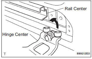
- Put in the slide door hinge center from the rear part of the slide door rail center.
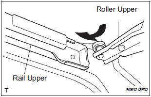
- Move the slide door forward and then put in the slide door roller upper into the cut area of the slide door rail upper.
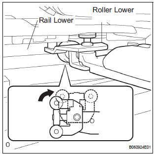
- Rotate the base of the slide door roller lower in the direction indicated by arrow in the illustration and then put in the roller into the cut area of the rail lower of the body.
- Install the open stop with the 2 nuts.
Torque: 7.0 N*m (71 kgf*cm, 62 in.*lbf)
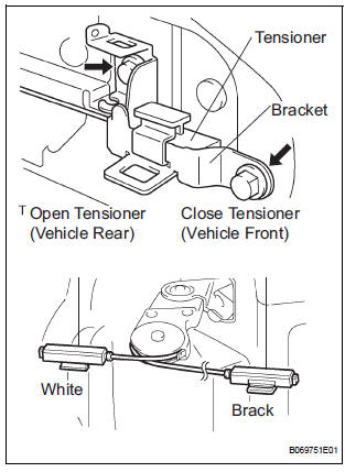
- Connect the open tensioner (color: white) to the bracket center No. 2 on the rear side of the vehicle.
HINT:
- The open tensioner (color: white) should be placed higher than the close tensioner (color: black) at their cross point.
- Be careful for the place where the tensioners are installed.
- Install the bracket center No. 2 connected to the
open tensioner (color: white) with the 2 bolts.
Torque: 8.0 N*m (82 kgf*cm, 71 in.*lbf)
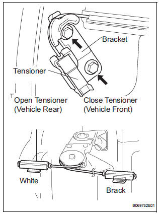
- Connect the close tensioner (color: black) to the bracket center No. 1 on the front side of the vehicle.
HINT:
- The close tensioner (color: black) should be placed lower than the open tensioner (color: white) at their cross point.
- Be careful for the place where the tensioner is installed.
- Install the bracket center No. 1 connected to the
close tensioner (color: black) with the 2 bolts.
Torque: 8.0 N*m (82 kgf*cm, 71 in.*lbf)
- Install the end moulding.
- Install the upper rail cushion to the rail upper.
- Install the wire with the bolt.
Torque: 7.0 N*m (71 kgf*cm, 62 in.*lbf)
- Connect the 2 connectors.
 Reassembly
1. INSTALL POWER SLIDE DOOR TOUCH SENSOR LH
Install the touch sensor with the 4 screws.
Connect the connector.
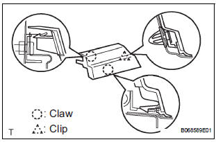
Fix the wire harness inside the door panel with the
clip.
2. INSTALL REA ...
 Slide door lock
INSPECTION
1. INSPECT SLIDE DOOR LOCK REMOTE CONTROL SUB-ASSEMBLY LH
Inspect the resistance of the switch.
Resistance
If the result is not as specified, replace the control
assembly.
...
Other materials:
Panel Switch Error/ Touch Switch Error
DTC 21-10 Panel Switch Error
DTC 21-11 Touch Switch Error
DTC 23-10 Panel Switch Error
DTC 23-11 Touch Switch Error
DTC 24-10 Panel Switch Error
DTC 24-11 Touch Switch Error
DTC 25-10 Panel Switch Error
DTC 25-11 Touch Switch Error
DESCRIPTION
INSPE ...
Canceling the power sliding door system (vehicles with power
sliding doors)
Turn the main switch off to disable
the power sliding door system.
Off
The sliding doors can only be
opened and closed manually.
On*
The power sliding door can be
opened and closed with the power
sliding door switches for the front
occupants or wireless remote control
even if ...
Removal
1. Drain automatic transaxle fluid
(a) Remove the drain plug, gasket and drain ATF.
(b) Install a new gasket and the drain plug.
Torque: 49 N*m (500 kgf*cm, 36 ft.*lbf)
2. Drain transfer oil (for 4wd)
Hint:
(see page tf-8)
3. Remove front wheel
4. REMOVE FRONT AXLE HUB LH NUT
(a) Us ...
