Toyota Sienna Service Manual: Read vin (vehicle identification number)
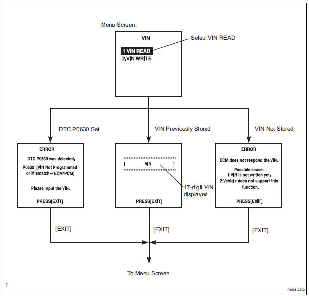
(a) The VIN reading process is shown in the flowchart below. Reading the VIN stored in the ECM is necessary when comparing it to the VIN provided with the vehicle.
(b) Read the VIN using the intelligent tester.
(c) Check the vehicle's VIN.
(d) Connect the intelligent tester to the DLC3.
(e) Turn the ignition switch to the ON position.
(f) Turn the tester ON.
(g) Enter the following menus: DIAGNOSIS / ENHANCED OBD II / VIN.
 Input instructions
(a) The general VIN input instructions using the
intelligent tester are shown below:
(b) The arrow buttons (UP, DOWN, RIGHT and LEFT)
and numerical buttons (0 to 9) are used to input the
VIN.
( ...
 Write vin
(a) The VIN writing process is shown in the flowchart
below. This process allows the VIN to be input into
the ECM. If the ECM is changed, or the ECM VIN
and Vehicle VIN do not match, the VIN can be ...
Other materials:
Removal
1. DISCONNECT CABLE FROM NEGATIVE BATTERY
TERMINAL
2. REMOVE REAR NO. 2 SEAT LEG SIDE GARNISH SUB-ASSEMBLY
Disengage the 9 clips and remove the rear No. 2
seat leg side garnish sub-assembly.
Remove the 9 clips from the rear No. 2 seat leg side
garnish sub-assembly.
3. ...
How to proceed with
troubleshooting
1 VEHICLE BROUGHT TO WORK SHOP
2 CUSTOMER PROBLEM ANALYSIS
3 CHECK BODY MULTIPLEX COMMUNICATION SYSTEM
Check for the DTC outputs.
4 DTC CHECK
5 DTC CHART
6 PROBLEM SYMPTOMS TABLE
7 TERMINAL OF ECU
8 CIRCUIT INSPECTION
9 IDENTIFICATION OF PROBLEM
10 REPAIR OR REPLACE
11 CONFIRMATION T ...
Message Settings
Display the “Phone/Message Settings” screen.
Select “Messaging Settings”.
Select the desired item to be set.
Set automatic message
transfer on/off.
Set automatic message
readout on/off.
Set the SMS/MMS notification
popup on/off.
Set the e-mail notification
pop ...
