Toyota Sienna Service Manual: Installation
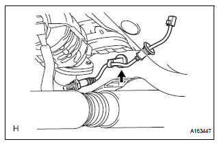
1. INSTALL AIR FUEL RATIO SENSOR (for Bank 2 Sensor 1)
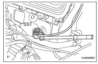
(a) Using SST, install the sensor to the exhaust manifold LH.
SST 09224-00010
Torque: 40 N*m (408 kgf*cm, 30 ft.*lbf) for use with SST 44 N*m (449 kgf*cm, 32 ft.*lbf) for use without SST
HINT:
- Use a torque wrench with a fulcrum length of 30 cm (11.81 in.).
- Make sure that SST and wrench are connected in a straight line.
(b) Connect the sensor connector.
2. INSTALL AIR FUEL RATIO SENSOR (for Bank 1 Sensor 1)
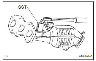
(a) Using SST, install the sensor to the exhaust manifold RH.
SST 09224-00010
Torque: 40 N*m (408 kgf*cm, 30 ft.*lbf) for use with SST 44 N*m (449 kgf*cm, 32 ft.*lbf) for use without SST
HINT:
- Use a torque wrench with a fulcrum length of 30 cm (11.81 in.).
- Make sure that SST and wrench are connected in a straight line.
3. INSTALL EXHAUST MANIFOLD RH
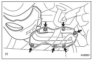
(a) Install the exhaust manifold RH with a new gasket and 6 nuts.
Torque: 21 N*m (214 kgf*cm, 15 ft.*lbf)
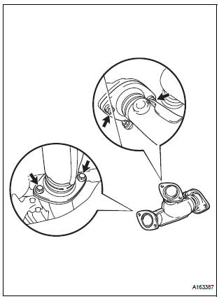
4. INSTALL CENTER EXHAUST PIPE ASSEMBLY
(a) Check compression springs.
(1) Check the compression springs using vernier calipers.
Specified length: 38.86 mm (1.5299 in.)
HINT:
If the result is not as specified, replace the compression spring.
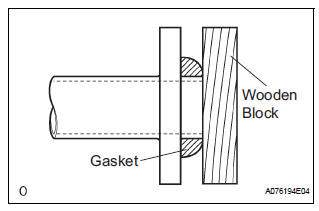
(b) Install the gasket.
(1) Install a new gasket by hand onto the front exhaust pipe assembly.
(2) Using a plastic hammer and wooden block, tap in the new gasket until its surface is flush with the front exhaust pipe.
NOTICE:
|
(c) Install 2 new gaskets to the front exhaust pipe assembly.
(d) Install the front exhaust pipe assembly with the 2 nuts and 2 bolts.
Torque: Bolt 43 N*m (440 kgf*cm, 32 ft.*lbf) Nut 62 N*m (632 kgf*cm, 46 ft.*lbf)
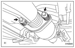
(e) Install the center exhaust pipe assembly with the 2 compression springs and 2 bolts.
Torque: 43 N*m (438 kgf*cm, 32 ft.*lbf)
(f) Attach the clip.
(g) Connect the heated oxygen sensor (for Bank 1 Sensor 2) connector.
5. CONNECT CABLE TO NEGATIVE BATTERY TERMINAL 6. INSPECT FOR EXHAUST GAS LEAK
 Inspection
1. Inspect air fuel ratio sensor
(A) measure the resistance of the sensor.
Standard resistance
If the resistance is not as specified, replace the
sensor.
...
 Heated oxygen sensor (for 2wd)
Components
Removal
1. DISCONNECT CABLE FROM NEGATIVE BATTERY
TERMINAL
CAUTION:
Wait at least 90 seconds after disconnecting the
cable from the nagative (-) battery terminal to
...
Other materials:
Removal
1. REMOVE REAR DOOR SCUFF PLATE LH
2. REMOVE REAR DOOR WEATHERSTRIP LH
3. REMOVE BACK DOOR WEATHERSTRIP
4. REMOVE BACK DOOR SCUFF PLATE
5. REMOVE QUARTER TRIM FRONT PANEL ASSEMBLY LH
6. REMOVE VOLTAGE INVERTER ASSEMBLY
Disconnect the connector.
Remove the 2 bolts and the v ...
Throttle Actuator Control Motor Current Range
/ Performance
DTC P2118 Throttle Actuator Control Motor Current Range
/ Performance
DESCRIPTION
The ETCS (Electronic Throttle Control System) has a dedicated power supply
circuit. The voltage (+BM)
is monitored and when it is low (less than 4 V), the ECM determines that there
is a malfunction in the
ETCS ...
Disassembly
1. REMOVE RH SEAT REAR SEAT RECLINING COVER
Remove the 2 screws.
Remove the RH seat rear seat reclining cover by
pulling it out in the arrow mark direction shown in
the illustration.
2. REMOVE LH SEAT REAR SEAT RECLINING COVER
Remove the 2 screws.
R ...
