Toyota Sienna Service Manual: Installation
1. INSTALL HEATED OXYGEN SENSOR (for Bank 2 Sensor 2)
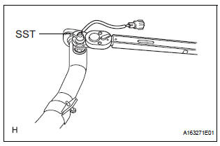
(a) Using SST, install the heated oxygen sensor to the front exhaust pipe.
SST 09224-00010
Torque: 40 N*m (408 kgf*cm, 30 ft.*lbf) for use with SST
44 N*m (449 kgf*cm, 32 ft.*lbf) for use without SST
HINT:
- Use a torque wrench with a fulcrum length of 30 cm (11.81 in.).
- Make sure that SST and a wrench are connected in a straight line.
2. INSTALL FRONT EXHAUST PIPE ASSEMBLY
(a) Install 2 new gaskets to the front exhaust pipe assembly.
(b) Install the front exhaust pipe assembly with the 2 bolts and 2 nuts.
Torque: Bolt 43 N*m (440 kgf*cm, 32 ft.*lbf)
Nut 62 N*m (632 kgf*cm, 46 ft.*lbf)
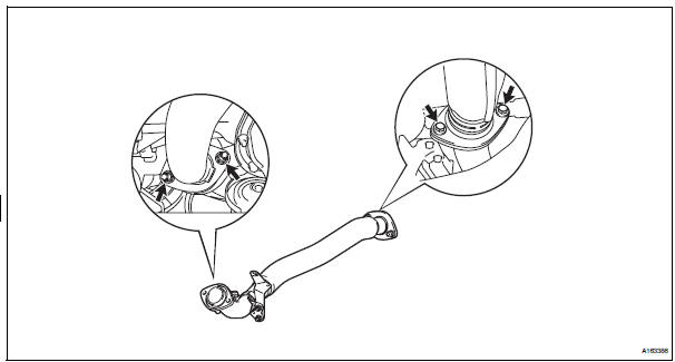
(c) Install the No. 1 exhaust pipe support bracket with 2 new nuts.
Torque: 21 N*m (214 kgf*cm, 15 ft.*lbf)
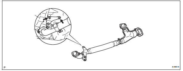
(d) Connect the heated oxygen sensor (for Bank 2 sensor 2) connector.
3. INSTALL HEATED OXYGEN SENSOR (for Bank 1 Sensor 2)
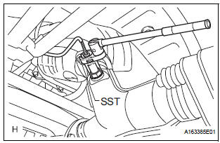
(a) Using SST, install the heated oxygen sensor.
SST 09224-00010
Torque: 40 N*m (408 kgf*cm, 30 ft.*lbf) for use with SST 44 N*m (449 kgf*cm, 32 ft.*lbf) for use without SST
(b) Connect the heated oxygen sensor (for Bank 1 Sensor 2) connector.
HINT:
- Use a torque wrench with a fulcrum length of 30 cm (11.81 in.).
- Make sure that SST and a wrench are connected in a straight line.
4. CONNECT CABLE TO NEGATIVE BATTERY TERMINAL
5. INSPECT FOR EXHAUST GAS LEAK
 Inspection
1. Inspect heated oxygen sensor (for bank 1
sensor 2)
(a) Measure the resistance of the sensor.
Standard resistance
If the resistance is not as specified, replace the
sensor.
2. HEATED OXY ...
 Fuel tank cap
Inspection
1. Inspect fuel tank cap assembly
(A) visually check that the cap and gasket are not
deformed or damaged.
If the result is not as specified, replace the cap
assembly or gasket. ...
Other materials:
Evaporative Emission System
DTC P043E Evaporative Emission System Reference Orifice
Clog Up
DTC P043F Evaporative Emission System Reference Orifice
High Flow
DTC P2401 Evaporative Emission System Leak Detection
Pump Control Circuit Low
DTC P2402 Evaporative Emission System Leak Detection
Pump Control Circuit High
DTC P ...
Removal
1. REMOVE ENGINE ASSEMBLY WITH TRANSAXLE
HINT:
See page EM-26
2. REMOVE OIL LEVEL GAUGE GUIDE SUBASSEMBLY
(See page EM-39)
3. REMOVE NO. 1 OIL PIPE (See page EM-77)
4. REMOVE OIL PIPE (See page EM-77)
5. REMOVE CRANKSHAFT PULLEY (See page EM-79)
6. SEPARATE OIL COOLER PIPE
(a) Remove th ...
Problem symptoms table
ENTIRE SYSTEM
METER GAUGES
WARNING LIGHTS
INDICATOR LIGHTS
BUZZER
ACCESSORY METER ASSEMBLY
...
