Toyota Sienna Service Manual: No Communication in Immobiliser System
DTC B2796 No Communication in Immobiliser System
DTC B2798 Communication Malfunction No. 2
DESCRIPTION
These codes are stored in the memory when a key that does not have a transponder chip is inserted or if communication between the key and transponder key ECU is impossible.
|
DTC No. |
DTC Detection Condition |
Trouble Area |
|
B2796 |
No communication |
|
|
B2798 |
Communication error |
|
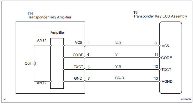
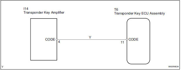
WIRING DIAGRAM
INSPECTION PROCEDURE
1 READ VALUE OF INTELLIGENT TESTER
- Connect the intelligent tester (with CAN VIM) to the DLC3.
- Turn the ignition switch on and turn the intelligent tester main switch on.
- Select IMMOBILISER in the DATA LIST and read the value displayed on the intelligent tester.
Transponder key ECU:
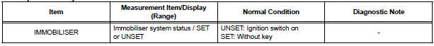
OK: UNSET (Ignition switch on) appears on the screen.
2 CHECK KEYS
- Insert the vehicle's other key into the ignition key cylinder.
- Check that the engine starts with this key.
OK: The engine starts
3 READ VALUE OF INTELLIGENT TESTER
- Connect the intelligent tester (with CAN VIM) to the DLC3.
- Turn the ignition switch on and turn the intelligent tester main switch on.
- Select ANTENNA COIL in the DATA LIST and read the value displayed on the intelligent tester
Transponder key ECU:
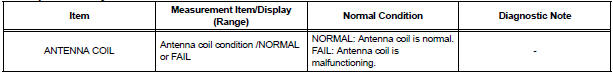
OK: NORMAL (Antenna coil is normal) appears on the screen.
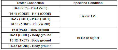
4 CHECK HARNESS AND CONNECTOR (TRANSPONDER KEY ECU ASSEMBLY - TRANSPONDER KEY AMPLIFIER)
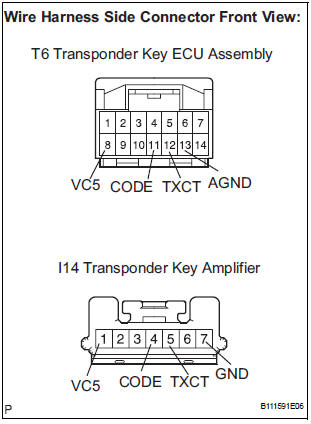
- Disconnect the T6 ECU and I14 amplifier connectors.
- Measure the resistance according to the value(s) in the table below.
Resistance
5 INSPECT TRANSPONDER KEY ECU ASSEMBLY
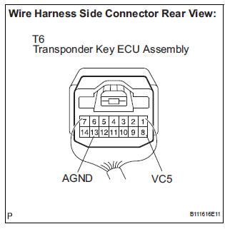
- Reconnect the T6 ECU and I14 amplifier connectors.
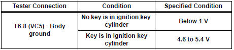
- Measure the voltage according to the value(s) in the table below.
Voltage
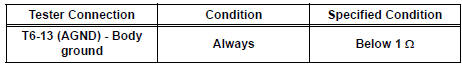
- Measure the resistance according to the value(s) in the table below.
Resistance
6 REPLACE TRANSPONDER KEY AMPLIFIER
- After replacing the transponder key amplifier with a normally functioning transponder key amplifier, check that the engine starts.
OK: The engine starts.
END (TRANSPONDER KEY AMPLIFIER DEFECTIVE)
DTC B2797 Communication Malfunction No. 1
DESCRIPTION
This DTC is output when an error occurs in normal communication.
HINT: Some noise found in the communication line.
|
DTC No. |
DTC Detection Condition |
Trouble Area |
|
B2797 |
Keys are positioned too close to each other, or noise occurred in communication line. |
|
WIRING DIAGRAM
INSPECTION PROCEDURE
1 CHECK KEY
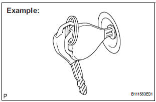
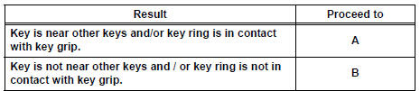
- Check whether the ignition key being used is near other ignition keys, as shown in the illustration. Also, check whether the key ring is in contact with the key grip.
Result
2 CHECK DTC OUTPUT
- Delete the DTC
- Insert the key into the ignition key cylinder.
- Check that no code is output.
OK: No DTC is output.
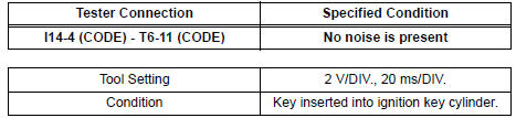
3 CHECK TRANSPONDER KEY AMPLIFIER
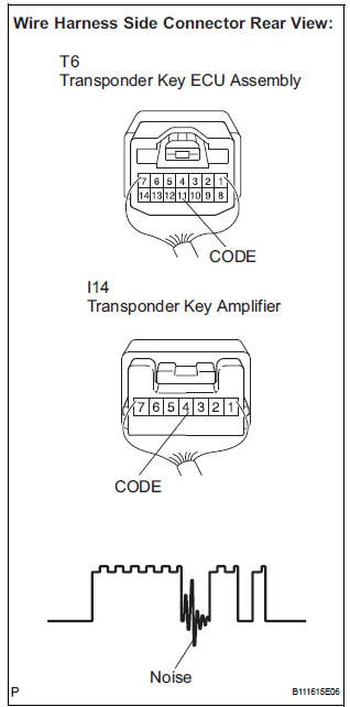
- Using an oscilloscope or the intelligent tester, check the
waveform between the terminals of the I14 amplifier and
T6 ECU connector.
Check that no noise is included in the waveform (an example of noise is shown on the left).
- Check that no noise is included in the waveform (an example of noise is shown on the left).
Result
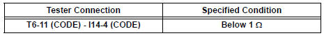
4 CHECK HARNESS AND CONNECTOR (TRANSPONDER KEY ECU - TRANSPONDER KEY AMPLIFIER)
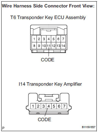
- Disconnect the T6 ECU and I14 amplifier connectors.
- Measure the resistance according to the value(s) in the table below.
Resistance
5 REPLACE TRANSPONDER KEY AMPLIFIER
- After replacing the transponder key amplifier with a normally functioning transponder key amplifier, check that the engine starts.
OK: The engine starts
END (TRANSPONDER KEY AMPLIFIER DEFECTIVE)
 Unmatched Key Code
DTC B2795 Unmatched Key Code
DESCRIPTION
This DTC is output when a key with a code that has not been registered in the
ECU is inserted into the
ignition key cylinder.
DTC No.
D ...
 Engine Immobiliser System Malfunction
DTC B2799 Engine Immobiliser System Malfunction
DESCRIPTION
This DTC is output when the ECM detects errors in communication between the
transponder key ECU
and the ECM, or in the communication li ...
Other materials:
Black Screen
INSPECTION PROCEDURE
1 CHECK DISPLAY SETTING
Check that the display is not in "Screen OFF" mode.
OK:
The display setting is not in "Screen OFF" mode.
2 CHECK IMAGE QUALITY SETTING
Check that the screen color quality can be set.
OK:
Setting is possible.
PRESS PA ...
Removal
1. DISCONNECT CABLE FROM NEGATIVE BATTERY
TERMINAL
2. REMOVE HEATED OXYGEN SENSOR (for Bank 1
Sensor 2) (See page EC-38)
3. REMOVE TAIL EXHAUST PIPE ASSEMBLY
(a) Remove the 2 bolts.
(b) Disconnect the 4 exhaust pipe supports and remove
the tail exhaust pipe assembly.
(c) Remove the gas ...
Casual speech recognization
Due to natural language speech recognition technology, this system
enables recognition of a command when spoken naturally. However,
the system cannot recognize every variation of each command.
In some situations, it is possible to omit the command for the procedure
and directly state the desir ...
