Toyota Sienna Service Manual: Installation
1. INSTALL TIMING CHAIN CASE OIL SEAL
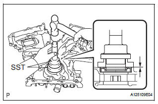
(a) Using SST, tap in a new oil seal until its surface is flush with the timing chain case edge.
SST 09223-22010, 09506-35010
NOTICE:
|
2. INSTALL TIMING CHAIN COVER SUB-ASSEMBLY
(a) Apply seal packing in a continuous line to the engine unit as shown in the following illustration.
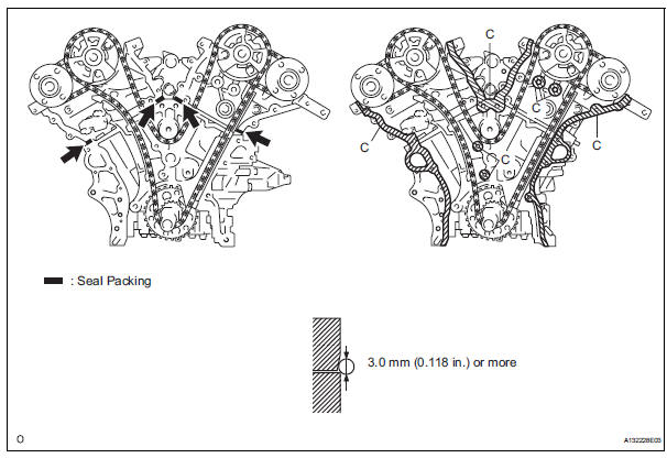
Seal packing: Toyota Genuine Seal Packing Black, Three Bond 1207B or equivalent Seal diameter: 3.0 mm (0.118 in.)
NOTICE:
|
(b) Apply seal packing in a continuous line to the timing chain cover as shown in the following illustration.
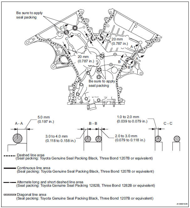
Seal packing: Toyota Genuine Seal Packing Black, Three
Bond 1207B or equivalent
Toyota Genuine Seal Packing 1282B, Three
Bond 1282B or equivalent
NOTICE:
|
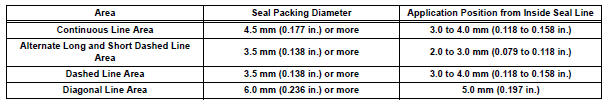
Apply seal packing as follows
(c) Install a new gasket.
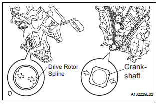
(d) Align the oil pump's drive rotor spline and the crankshaft as shown in the illustration. Install the spline and chain cover to the crankshaft.
(e) Temporarily tighten the timing chain cover with the 23 bolts and 2 nuts.
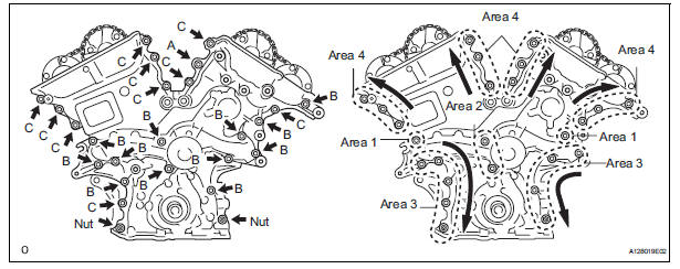
Bolt length 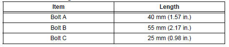
| NOTICE: Make sure that there is no oil on the bolt threads. |
(f) Fully tighten the bolts in: Area 1 and Area 2.
Torque: 21 N*m (214 kgf*cm, 15 ft.*lbf) (g) Fully tighten the bolts and nuts in: Area 3.
Torque: 21 N*m (214 kgf*cm, 15 ft.*lbf) HINT: Tighten the bolts and nuts from top to bottom as shown in the illustration.
(h) Fully tighten the bolts in: Area 4.
Torque: Bolt A 43 N*m (438 kgf*cm, 32 ft.*lbf) Except bolt A 21 N*m (214 kgf*cm, 15 ft.*lbf)
HINT: Tighten the bolts from bottom to top as shown in the illustration.
3. INSTALL WATER INLET HOUSING (See page CO-13) 4. INSTALL OIL PAN SUB-ASSEMBLY (See page EM- 160) 5. INSTALL OIL STRAINER SUB-ASSEMBLY (See page EM-161) 6. INSTALL NO. 2 OIL PAN SUB-ASSEMBLY (See page EM-162) 7. INSTALL CYLINDER HEAD COVER SUB-ASSEMBLY (for Bank 1) (See page EM-163) 8. INSTALL CYLINDER HEAD COVER SUB-ASSEMBLY (for Bank 2) (See page EM-163) 9. INSTALL CRANKSHAFT PULLEY (See page EM-166) 10. INSTALL OIL COOLER PIPE
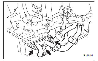
(a) Install a new gasket to the oil pan sub-assembly.
(b) Install the oil cooler pipe with the bolt and 2 nuts.
Torque: 21 N*m (214 kgf*cm, 16 ft.*lbf)
11. INSTALL NO. 1 OIL PIPE (See page EM-167) 12. INSTALL OIL PIPE (See page EM-168) 13. INSTALL OIL LEVEL GAUGE GUIDE SUBASSEMBLY (See page EM-48) 14. INSTALL ENGINE ASSEMBLY WITH TRANSAXLE
HINT: See page EM-44
 Reassembly
1. INSTALL OIL PUMP COVER
(a) Coat the drive and driven rotors with engine oil and
place them into the timing chain cover with the
marks facing outward (oil pump cover side). Check
that the ro ...
 Engine oil cooler
Components
...
Other materials:
Removal
HINT:
Replace the RH side by the same procedures as the LH side.
1. REMOVE REAR WHEEL
2. REMOVE REAR AXLE SHAFT LH NUT (See page DS-
22)
3. SEPARATE REAR DISC BRAKE CALIPER
ASSEMBLY LH
(a) Removing the 2 bolts, separate the rear disc brake
caliper assembly LH.
4. REMOVE REAR DISC
5. SEPARA ...
Terminals of ECU
1. JUNCTION CONNECTOR
Junction connector
with VSC
HINT:
*1: with Dynamic laser cruise control
without VSC
CAN junction connector (with VSC)
with VSC
The connection diagram of the components which
are connected to the CAN junction connector.
2. DLC3
...
Removal
NOTICE:
When installing, coat the parts indicated by the arrows
with power steering fluid or molybdenum disulfide
lithium base grease (See page PS-21).
1. INSPECT CENTER FRONT WHEEL
2. REMOVE FRONT WHEEL
3. SEPARATE TIE ROD ASSEMBLY LH
SST 09628-62011
4. SEPARATE TIE ROD ASSEMBLY RH
SST 096 ...
