Toyota Sienna Service Manual: Installation
1. INSTALL FUEL INJECTOR ASSEMBLY
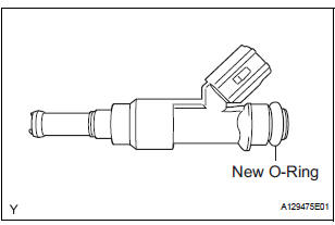
(a) Apply a light coat of spindle oil or gasoline to new Orings, and install them to each injector.
(b) Apply a light coat of spindle oil or gasoline where the fuel delivery pipe contacts the O-ring.
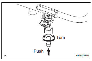
(c) Push the fuel injector while turning it to install the injector in the fuel delivery pipe.
(d) Position the fuel injector connector outward.
NOTICE:
|
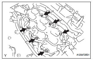
(e) Install 6 new insulators to the intake manifold.
(f) Place the fuel delivery pipe which has the 6 fuel injectors installed to it in position on the intake manifold.
| NOTICE: Be careful not to drop the fuel injectors when installing the fuel delivery pipe. |
(g) Temporarily install the 5 bolts which are used to hold the fuel delivery pipe to the intake manifold.
| NOTICE: After installing the fuel injectors, check that they turn smoothly. If not, reinstall the injectors with new O-rings. |
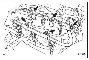
(h) Tighten the 5 bolts which are used to hold the fuel delivery pipe to the intake manifold.
Torque: 21 N*m (214 kgf*cm, 15 ft.*lbf)
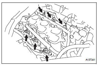
(i) Connect the 6 fuel injector connectors.
2. CONNECT FUEL TUBE SUB-ASSEMBLY
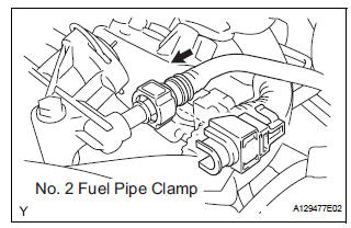
(a) Push in the tube connector onto the pipe until the tube connector makes a "click" sound.
NOTICE:
|
(b) Install the No. 2 fuel pipe clamp.
3. INSTALL INTAKE AIR SURGE TANK ASSEMBLY
NOTICE:
DO NOT apply oil to the bolts listed below:
 |
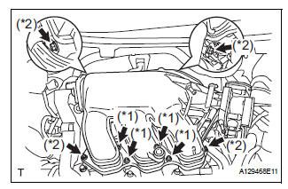
(a) Install a new gasket to the intake air surge tank assembly.
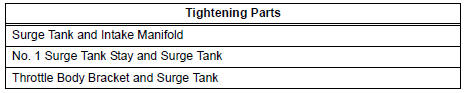
(b) Using a 5 mm hexagon socket wrench, install the 4 bolts. (*1) Torque: 18 N*m (184 kgf*cm, 13 ft.*lbf) (c) Install the intake air surge tank assembly with the 2 nuts and 2 bolts. (*2)
Torque: Nut 16 N*m (163 kgf*cm, 12 ft.*lbf) Bolt 21 N*m (214 kgf*cm, 15 ft.*lbf)
(d) Connect the connector.
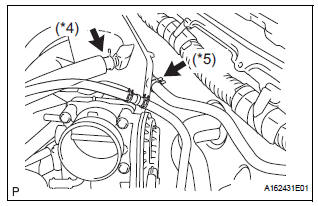
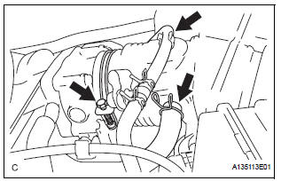
(e) Connect the union to check valve hose. (*1) (f) Connect the No. 1 ventilation hose. (*2)
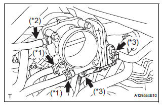
(g) Install the clamp and connect the throttle with motor body assembly connector. (*3) (h) Connect the vapor feed hose assembly. (*4) (i) Connect the 2 water by-pass hoses to the throttle with motor body assembly. (*5)
4. INSTALL AIR CLEANER CAP SUB-ASSEMBLY
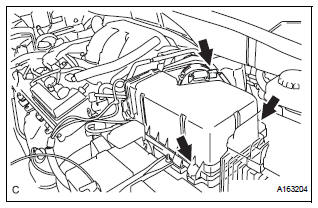
(a) Install the 2 bolts and air cleaner cap sub-assembly.
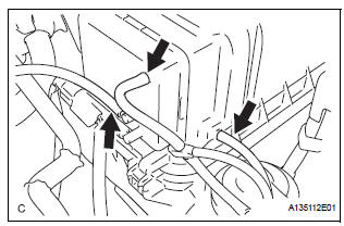
(b) Connect the No. 2 ventilation hose and air cleaner hose band.
(c) Connect the vacuum hose (EVAP) to the air cleaner hose.
(d) Connect the 3 vacuum hoses.
5. ADD ENGINE COOLANT (See page CO-7)
6. CONNECT CABLE TO NEGATIVE BATTERY TERMINAL 7. INSPECT FOR ENGINE COOLANT LEAK (See page CO-1) 8. INSTALL NO. 1 ENGINE UNDER COVER 9. INSPECT FOR FUEL LEAK (See page FU-7)
10. INSTALL V-BANK COVER SUB-ASSEMBLY (See page EM-63) 11. INSTALL COWL TOP PANEL SUB-ASSEMBLY OUTER FRONT
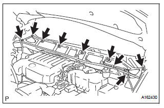
(a) Install the 7 bolts and the cowl top panel subassembly outer front.
Torque: 7.5 N*m (76 kgf*cm, 66 in.*lbf) (b) Connect the fuel pump resistor connector.
(c) Connect the wire harness clamp.
12. INSTALL NO. 1 COWL TOP TO COWL BRACE INNER

(a) Install the 2 bolts and the No.1 cowl top to cowl brace inner.
Torque: 7.5 N*m (76 kgf*cm, 66 in.*lbf)
13. INSTALL WINDSHIELD WIPER MOTOR AND LINK ASSEMBLY (See page WW-6) 14. INSTALL FRONT WIPER ARM LH (See page WW-6) 15. INSTALL FRONT WIPER ARM RH (See page WW-7)
 Inspection
1. INSPECT FUEL INJECTOR ASSEMBLYV
(A) inspect the injector resistance.
(1) Using an ohmmeter, measure the resistance
between the terminals.
Standard resistance
If the resistance is not a ...

Other materials:
Passenger Side Outer Mirror ECU
DTC B1208 Passenger Side Outer Mirror ECU
DESCRIPTION
This DTC is detected when communication between the outer mirror control ECU
RH and multiplex
network gateway ECU stops for more than 10 seconds.
DTC No.
DTC Detecting Condition
Trouble Area
B1208
Pa ...
Auto Up Operation does not Fully Close Power Window (Jam
Protection Function is Activated)
DESCRIPTION
If AUTO UP operation does not fully close the power window, the following
conditions may be the cause.
The reset of the power window motor has not been completed,
resulting in activation of the jam
protection function.
The memory of the power window switch misse ...
Battery
Check the battery as follows:
Battery exterior
Make sure that the battery terminals are not corroded and that
there are no loose connections, cracks, or loose clamps.
Terminals
Hold-down clamp
Before recharging
When recharging, the battery produces hydrogen gas which is flammable an ...
