
Toyota Sienna Service Manual: Installation
1. INSTALL IGNITION SWITCH ASSEMBLY
(a) Install the ignition switch with the 2 screws.
(b) Install the ignition switch connector.
2. INSTALL STEERING COLUMN COVER LOWER
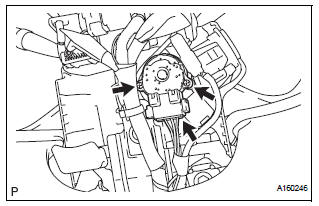
(a) Attach the 4 claws to install the steering column cover lower.
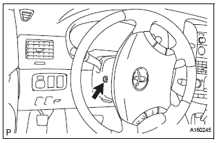
(b) Insert the key into the ignition key cylinder and release the steering lock.
(c) Turn the steering wheel counterclockwise and install the screw.
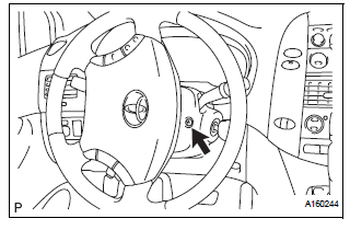
(d) Turn the steering wheel clockwise and install the screw.
3. CONNECT CABLE TO NEGATIVE BATTERY TERMINAL
 Inspection
1. Inspect ignition switch assembly
(a) Measure the resistance of the switch.
Standard resistance
If the result is not as specified, replace the switch
assembly. ...
 2Gr-fe charging
...
Other materials:
Freeze frame data
1. DESCRIPTION
The ECM records vehicle and driving condition
information as freeze frame data the moment a DTC
is stored. When troubleshooting, freeze frame data
can be helpful in determining whether the vehicle
was running or stopped, whether the engine was
warmed up or not, whe ...
Trip information
Type A
Press the “CAR� button.
Type B
Press the “APPS� button, and then select “Eco� on the screen.
If the “Past Record� screen is displayed, select “Trip Information�.
Reset the trip information data
Previous fuel consumption per
minute
Current fuel ...
Removal
1. DISCONNECT CABLE FROM NEGATIVE BATTERY
TERMINAL
2. REMOVE FRONT DOOR SCUFF PLATE LH
3. REMOVE COWL SIDE TRIM SUB-ASSEMBLY LH
4. REMOVE LOWER INSTRUMENT PANEL FINISH
PANEL SUB-ASSEMBLY LH (See page IP-6)
5. REMOVE TIRE PRESSURE WARNING RESET SWITCH
(a) Disengage the 2 claws and remove t ...
