Toyota Sienna Service Manual: Installation
1. INSTALL SHIFT LEVER ASSEMBLY
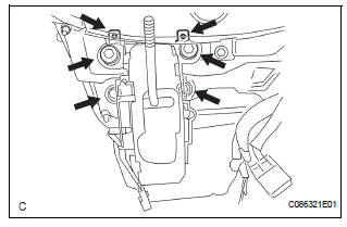
(a) Install shift lever assembly to the vehicle with the 4 bolts.
Torque: 21 N*m (214 kgf*cm, 15 ft.*lbf)
| NOTICE: Into datum hole of shift lever into datum pin of instrument lower. |
(b) Connect the 2 connectors to the shift lever assembly.
2. INSTALL TRANSMISSION CONTROL CABLE ASSEMBLY
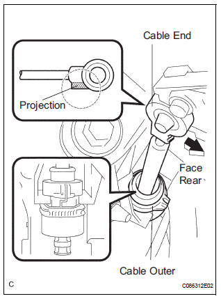
(a) Install the cable outer to the shift lever plate

(b) When installing the transmission control cable assembly on the shift lever plate, place the projection to the shift lever plate (FIG. 2).
Confirm that the spring in the shift cable outer has moved to the position (FIG. 3) shown in the illustration.
Confirm that the shift cable is installed on the shift lever plate properly.
NOTICE:
|
3. INSTALL INSTRUMENT CLUSTER FINISH PANEL SUB-ASSEMBLY LOWER CENTER
HINT: (See page IP-15)
4. INSTALL SHIFT LEVER CAP
(a) Install the shift lever cap to the floor shift position indicator housing assembly.
5. INSTALL POSITION INDICATOR HOUSING ASSEMBLY
(a) install the position indicator housing assembly to the instrument cluster finish panel assembly center.
6. INSTALL SHIFT LEVER KNOB SUB-ASSEMBLY
(a) install the shift lever knob sub-assembly.
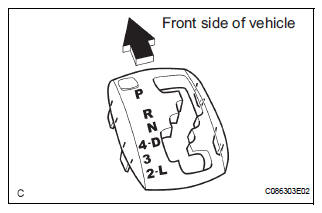
7. ADJUST SHIFT LEVER POSITION
HINT: (See page AX-149)
8. INSPECT SHIFT LEVER POSITION
HINT: (See page AX-148)
9. INSPECT KEY INTER LOCK OPERATION
HINT: (See page AX-142)
10. INSPECT SHIFT LOCK OPERATION
HINT: (See page AX-142)
11. INSPECT SHIFT LOCK RELEASE BUTTON OPERATION
HINT: (See page AX-142)
 Reassembly
1. Install position indicator slide cover
(a) Install the position indicator slide cover No.2 to the
position indicator slide cover.
2. INSTALL POSITION INDICATOR SLIDE COVER
(a) Install the p ...
Other materials:
Door Courtesy Switch Circuit
DESCRIPTION
The Multiplex network body ECU detects the condition of the door courtesy
switch assembly.
WIRING DIAGRAM
INSPECTION PROCEDURE
1 READ VALUE OF INTELLIGENT TESTER
Connect the intelligent tester to DLC3.
Turn the ignition switch to ON and push the intelligent
tester ...
Disassembly
1. REMOVE FRONT DISC BRAKE BUSH DUST BOOT
(a) Using soft jaws on the vise, hold the front disc brake
cylinder mounting LH in the vise through aluminum
plates.
(b) Using a screwdriver and hammer, remove the 2
front disc brake bush dust boots from the front disc
brake cylinder mounting LH. ...
How to proceed with
troubleshooting
HINT:
Troubleshoot in accordance with the procedures on the
following pages.
1 VEHICLE BROUGHT TO WORKSHOP
2 DTC CHECK
Check for DTCs and make a note of the code that is
output (See page MP-14).
Delete the DTC.
Check if the DTC is output once again when the problem
symptom is simulat ...
