Toyota Sienna Service Manual: Reassembly
1. Install position indicator slide cover
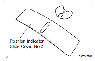
(a) Install the position indicator slide cover No.2 to the position indicator slide cover.
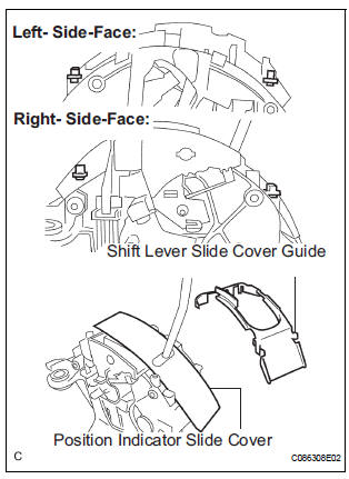
2. INSTALL POSITION INDICATOR SLIDE COVER
(a) Install the position indicator slide cover to the shift lever assembly.
(b) Install the shift lever slide cover guide to the shift lever assembly.
3. INSTALL POSITION INDICATOR LIGHT BULB
(a) Install the shift position indicator light bulb to the indicator light wire sub-assembly.
4. INSTALL INDICATOR LIGHT WIRE SUB-ASSEMBLY
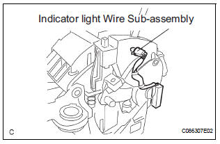
(a) Install the indicator light wire sub-assembly to the shift lever assembly.
 Adjustment
1. INSPECT SHIFT LEVER POSITION
(a) When shifting from P to R position only with ignition
switch ON and brake pedal, make sure that the
shifting lever moves smoothly and can be
moderately operated ...
 Installation
1. INSTALL SHIFT LEVER ASSEMBLY
(a) Install shift lever assembly to the vehicle with the 4
bolts.
Torque: 21 N*m (214 kgf*cm, 15 ft.*lbf)
NOTICE:
Into datum hole of shift lever into ...
Other materials:
Low Battery Positive Voltage
DTC C1241/41 Low Battery Positive Voltage
DESCRIPTION
WIRING DIAGRAM
INSPECTION PROCEDURE
1 INSPECT ECU-IG FUSE
(a) Remove the ECU-IG fuse from the driver side J/B.
(b) Check continuity of the ECU-IG fuse.
Standard resistance
2 CHECK BATTERY
(a) Check the positive battery volt ...
Data list / active test
HINT:
By accessing the DATA LIST displayed on the intelligent
tester, you can perform such functions as reading the values
of switches and sensors without removing any parts. Reading
the DATA LIST as the first step in troubleshooting is one
method to shorten labor time.
1. DATA LIST FOR CENTER ...
Reassembly
1. INSTALL REAR WHEEL CYLINDER CUP KIT
(a) Temporarily tighten the bleeder plug to the wheel
cylinder, and install the bleeder plug cap.
(b) Apply lithium soap base glycol grease to the 2 new
wheel cylinder cups and the 2 pistons.
(c) Install the 2 wheel cylinder cups to each piston.
...
