Toyota Sienna Service Manual: Installation
1. Install generator assembly
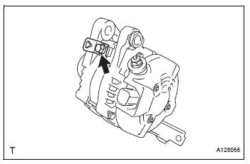
(a) Install the bracket with the bolt.
Torque: 20 N*m (204 kgf*cm, 15 ft.*lbf)
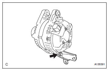
(b) Install the wire harness clamp stay.
Torque: 8.4 N*m (86 kgf*cm, 74 in.*lbf)
(c) Connect the wire harness clamp.
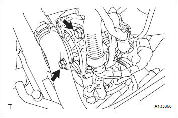
(d) Install the generator assembly to the cylinder block with the bolt.
Torque: 20 N*m (204 kgf*cm, 15 ft.*lbf)
(e) Install the 2 bolts.
Torque: 43 N*m (438 kgf*cm, 32 ft.*lbf)
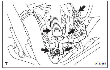
Connect the generator connector to the generator assembly.
(g) Install the generator wire with the nut.
Torque: 9.8 N*m (100 kgf*cm, 87 in.*lbf) (h) Install the terminal cap.
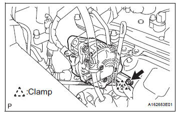
(i) Connect the 2 wire harness clamps.
(j) Connect the magnetic clutch connector to the compressor and magnetic clutch.
2. INSTALL V-RIBBED BELT (See page EM-7) 3. INSTALL RADIATOR ASSEMBLY WITH FAN SHROUD AND FAN MOTOR (See page CO-40) 4. INSTALL NO. 1 RADIATOR SUPPORT (See page CO- 40) 5. INSTALL RADIATOR SUPPORT CUSHION (See page CO-41) 6. REMOVE PRESSURE FEED TUBE ASSEMBLY (See page CO-41) 7. INSTALL HEADLIGHT BRACKET RH (See page CO- 41) 8. INSTALL RADIATOR SIDE DEFLECTOR RH (See page CO-41) 9. INSTALL HEADLIGHT ASSEMBLY RH (See page LI- 78) 10. CONNECT NO. 2 OIL COOLER OUTLET TUBE SUBASSEMBLY (See page CO-41) 11. INSTALL RADIATOR UPPER SUPPORT SUBASSEMBLY (See page CO-42) 12. CONNECT COOLING FAN ECU CONNECTOR (See page CO-42) 13. INSTALL HOOD LOCK SUPPORT SUB-ASSEMBLY (See page CO-43) 14. INSTALL HOOD LOCK ASSEMBLY (See page CO-43) 15. INSTALL HOOD LOCK RELEASE LEVER PROTECTOR (See page CO-44) 16. CONNECT NO. 2 RADIATOR HOSE (See page CO-44) 17. CONNECT NO. 1 RADIATOR HOSE (See page CO-44)
18. CONNECT RADIATOR RESERVE TANK HOSE OR PIPE (See page CO-44) 19. INSTALL NO. 1 AIR CLEANER INLET (See page EM- 59) 20. INSTALL FRONT BUMPER ENERGY ABSORBER 21. INSTALL FRONT BUMPER ASSEMBLY (See page ET- 9) 22. INSTALL BATTERY (See page EM-59) 23. INSTALL NO. 2 AIR CLEANER INLET (See page EM- 60) 24. ADD ENGINE COOLANT (See page CO-7) 25. INSPECT FOR COOLANT LEAK (See page CO-1) 26. ADD AUTOMATIC TRANSAXLE FLUID 27. CHECK AUTOMATIC TRANSAXLE FLUID (See page AX-123) 28. INSTALL FRONT FENDER APRON SEAL RH (See page EM-62) 29. INSTALL NO. 1 ENGINE UNDER COVER (See page EM-63) 30. INSTALL FRONT WHEEL RH Torque: 103 N*m (1050 kgf*cm, 76 ft.*lbf) 31. INSTALL V-BANK COVER SUB-ASSEMBLY (See page EM-63) 32. VEHICLE PREPARATION FOR HEADLIGHT AIM ADJUSTMENT (See page LI-71) 33. PREPARATION FOR HEADLIGHT AIMING (Using a tester) (See page LI-71) 34. PREPARATION FOR HEADLIGHT AIMING (Using a Screen) (See page LI-72)
35. HEADLIGHT AIMING INSPECTION (See page LI-74) 36. HEADLIGHT AIMING ADJUSTMENT (See page LI-75) 37. VEHICLE PREPARATION FOR FOG LIGHT AIM ADJUSTMENT (w/ Fog Light) (See page LI-82) 38. PREPARATION FOR FOG LIGHT AIMING (Using a Screen) (w/ Fog Light) (See page LI-83) 39. FOG LIGHT AIMING INSPECTION (w/ Fog Light) (See page LI-74) 40. FOG LIGHT AIMING ADJUSTMENT (w/ Fog Light) (See page LI-85)
 Reassembly
1. INSTALL GENERATOR ROTOR ASSEMBLY
(a) Place the drive end frame on the clutch pulley.
(b) Install the generator rotor assembly to the drive end
frame.
(c) Place a new generator washer ...

Other materials:
Front Occupant Classification Sensor RH Circuit
Malfunction
DTC B1781 Front Occupant Classification Sensor RH Circuit
Malfunction
DESCRIPTION
The front occupant classification sensor RH circuit consists of the occupant
classification ECU and the
front occupant classification sensor RH.
DTC B1781 is recorded when a malfunction is detected in the fron ...
Disassembly
HINT:
When the battery is reconnected, the back door is locked and
cannot be opened. Therefore, it is necessary to unlock the
back door using the door control switch or transmitter switch.
1. REMOVE BACK DOOR SCUFF PLATE (See page ET-
18)
2. REMOVE QUARTER TRIM PANEL ASSEMBLY
FRONT LH
3. REM ...
Front Speed Sensor RH Circuit
DESCRIPTION
The speed sensor detects wheel speed and transmits the appropriate signals to
the ECU. These signals
are used for control of the ABS control system. The front and rear rotors have
48 serrations each.
When the rotors rotate, the magnetic field generated by the permanent magne ...
