Toyota Sienna Service Manual: Installation
1. INSTALL PROPELLER W/CENTER BEARING SHAFT ASSEMBLY
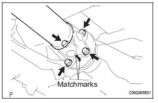
(a) Align the matchmarks on the propeller shaft assembly rear flange and differential companion flange, and connect the shaft with the 4 bolts, washers and nuts.
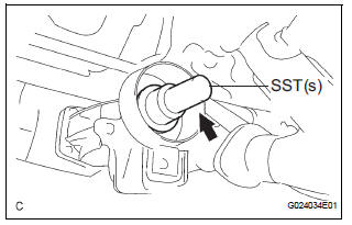
(b) Remove SST(s) from the extension housing.
(c) Insert the yoke into the extension housing.
NOTICE:
- Be careful not to damage the oil seal.
- Be careful not to damage the universal joint boot when installing the propeller shaft.
(d) Install the 2 adjusting shims and propeller shaft w/ center bearing, and loosely tighten the 4 bolts.
(e) Tighten the 4 nuts.
Torque: 74 N*m (750 kgf*cm, 54 ft.*lbf)
2. FULLY TIGHTEN PROPELLER W/CENTER BEARING SHAFT ASSEMBLY
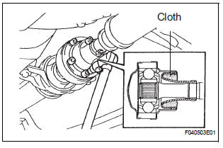
(a) Remove the cloth from the joint.
(b) Using a hexagon wrench (6 mm), tighten the 6 bolts.
Torque: 29 N*m (296 kgf*cm, 21 ft.*lbf)
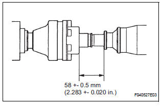
(c) With the vehicle unloaded, adjust the dimension between the rear side of the cover and shaft, as shown in the illustration.
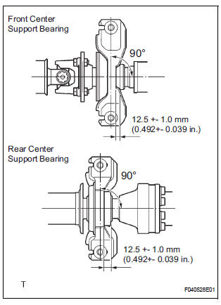
(d) Adjust the front and rear dimensions between the edge surface of the center support bearing and the edge surface of the cushion to 12.5 +- 1.0 mm (0.492 +- 0.039 in.) respectively as shown in the illustration, then torque the bolts.
Torque: 37 N*m (375 kgf*cm, 27 ft.*lbf) (e) Check that the center line of the bracket is at right angles to the shaft axial direction.
(f) If any vibration or noise occurs, perform joint angle check as follows and replace the adjusting shim with a proper one.
(1) Turn the propeller shaft several times by hand to stabilize the center support bearings.
(2) Using a jack, raise and lower the differential to stabilize the differential mounting cushion.
(3) Remove the transfer dynamic damper.
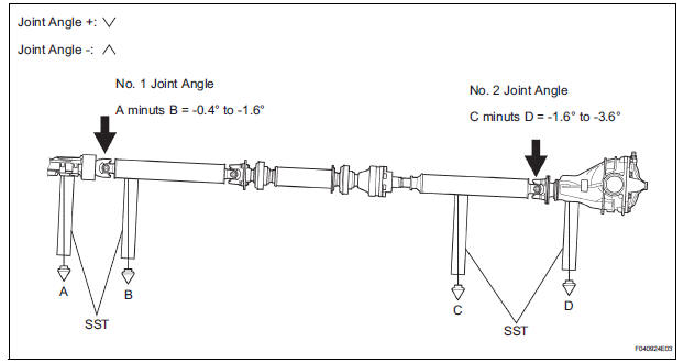
(4) Using SST(s), measure the installation angle of the transfer extension housing (A) and front propeller shaft (B).
SST 09370-50010 No. 1 joint angle: A minus B = -0.4° to -1.6°
(5) Using SST(s), measure the installation angle of the rear propeller shaft (C) and rear differential (D).
SST 09370-50010 No. 2 joint angle: C minus D = -1.6° to -3.6°
If the measured angle is not within the specification, adjust with the center support bearing adjusting shim.
Center support bearing adjusting shim
thickness
(g) Install the transfer dynamic damper.
Torque: 26 N*m (260 kgf*cm, 19 ft.*lbf)
3. INSTALL EXHAUST PIPE ASSEMBLY
(a) Install exhaust pipe assembly (See page EX-10).
 Reassembly
1. INSTALL CENTER SUPPORT BEARING ASSEMBLY NO.1
(a) Set the center support bearing assembly No. 1
(front) to the intermediate shaft, as shown in the
illustration.
(b) Install a new washer to ...
 Drive shaft
...
Other materials:
Installation
1. INSTALL REAR DOOR GLASS WEATHERSTRIP
Install the rear door glass weatherstrip.
2. INSTALL SLIDE DOOR WINDOW ASSEMBLY
3. INSTALL REAR DOOR GLASS RUN
4. INSTALL REAR DOOR TRIM BOARD SUBASSEMBLY
5. INSTALL SIDE TRIM BOARD COVER REAR
6. INSTALL REAR DOOR WINDOW FRAME SUBASSEMBLY
7. INSTA ...
Back Door Closer does not Operate
DESCRIPTION
The power back door ECU controls the back door closer system. In response to
the signals output from
the switches related to the back door lock, the back door latch activates the
closer motor.
HINT:
The back door closer system operates regardless of whether the power back door
...
TRAC OFF Indicator Light does not Come ON
DESCRIPTION
The skid control ECU is connected to the combination meter via CAN and
multiplex communications.
When the traction OFF switch is turned on, the TRAC OFF indicator light will
come on (for 2WD model).
WIRING DIAGRAM
Refer to TRAC OFF Indicator Light Remains ON (See page BC-157).
...
