Toyota Sienna Service Manual: Terminals of ecm
1. Ecm
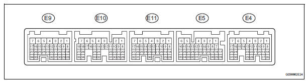
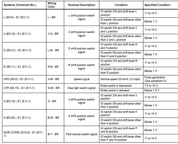
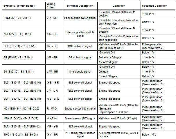
Hint: each ecm terminal's standard voltage is shown in the table below.
In the table, first follow the information under "condition".
Look under "symbols (terminal no.)" For the terminals to inspected. The standard voltage between the terminals is shown under "specific condition".
Use the illustration above as a reference for the ecm terminals.
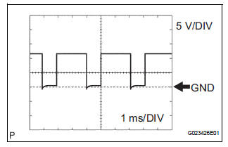
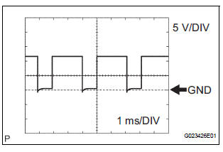
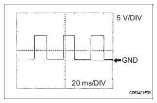
(a) Waveform 1
Reference: 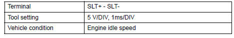
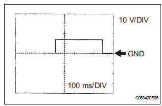
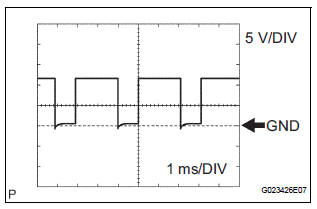
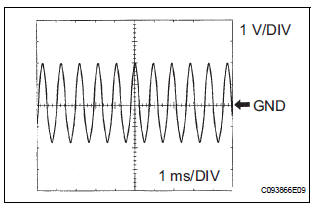
(b) Waveform 2
Reference: 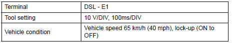
(c) Waveform 3
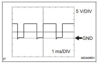
Reference: 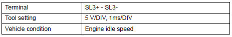
(d) Waveform 4
Reference: 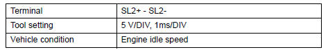
(e) Waveform 5
Reference: 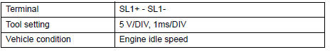
(f) Waveform 6
Reference: 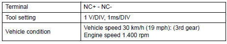
(g) Waveform 7
Reference: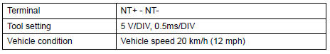
(h) Waveform 8
Reference: 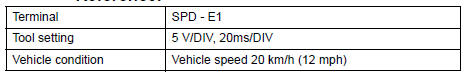
 Problem symptoms table
HINT:
If a normal code is displayed during the diagnostic trouble
code check although the trouble still occurs, check the
electrical circuits for each symptom in the order given in
the chart ...
 Diagnosis system
1. DESCRIPTION
(a) When troubleshooting OBD II vehicles, the only
difference from the usual troubleshooting procedure
is to connect an OBD II scan tool complying with
SAE J1987 or a intelligen ...
Other materials:
System description
1. DESCRIPTION OF POWER REAR NO. 2 SEAT WITH
STOWING FUNCTION
A power rear no. 2 seat with stowing function has
been adopted for the third-row seats.
The power rear no. 2 seat with stowing function
electrically stows and returns the seat when the
power folding seat switch is ...
Installation
1. INSTALL STEERING ANGLE SENSOR
(a) Install the steering sensor onto the spiral cable.
2. PLACE FRONT WHEELS FACING STRAIGHT AHEAD
3. INSTALL SPIRAL CABLE SUB-ASSEMBLY (See page
RS-434)
4. INSTALL STEERING COLUMN COVER LWR (See
page RS-435)
5. CENTER SPIRAL CABLE (See page RS-435)
6. IN ...
Steering Angle Sensor Zero Point Malfunction
DTC C1290/66 Steering Angle Sensor Zero Point Malfunction
DESCRIPTION
The skid control ECU acquires steering angle sensor zero point every time the
ignition switch is turned to
the ON position and the vehicle is driven at 35 km/h (22 mph) or more for
approximately 5 seconds. The
ECU also sto ...
