Toyota Sienna Service Manual: Reassembly
1. INSTALL CENTER SUPPORT BEARING ASSEMBLY NO.1
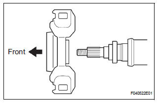
(a) Set the center support bearing assembly No. 1 (front) to the intermediate shaft, as shown in the illustration.
(b) Install a new washer to the intermediate shaft.
NOTICE: Be sure to install the bearing in the correct direction.
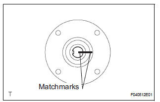
(c) Align the matchmarks on the front flange and shaft, and place the flange on the shaft.
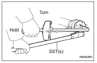
(d) Using SST(s) to hold the front flange, press the center support bearing assembly No. 1 (front) into the position by tightening down with a new nut and plate washer.
SST 09330-00021 Torque: 181 N*m (1,850 kgf*cm, 134 ft.*lbf)
(e) Loosen the nut.
(f) Torque the nut again.
Torque: 69 N*m (700 kgf*cm, 51 ft.*lbf)
(g) Using a chisel and a hammer, stake the nut.
2. INSTALL CENTER SUPPORT BEARING ASSEMBLY NO.1
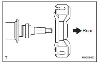
(a) Set the center support bearing assembly No. 1 (rear) on the shaft, as shown in the illustration.
(b) Install a new washer to the shaft.
NOTICE: Be sure to install the bearing in the correct direction.
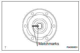
(c) Align the matchmarks on the rear flange and shaft, and place the flange on the shaft.
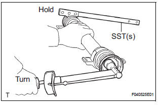
(d) Using SST(s) to hold the front flange, press the center support bearing assembly No. 1 (rear) into the position by tightening down with a new nut and plate washer.
SST 09330-00021 Torque: 181 N*m (1,850 kgf*cm, 134 ft.*lbf)
(e) Loosen the nut.
(f) Torque the nut again.
Torque: 69 N*m (700 kgf*cm, 51 ft.*lbf)
(g) Using a chisel and a hammer, stake the nut.
3. INSTALL INTERMEDIATE SHAFT
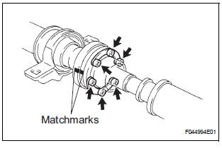
(a) Align the matchmarks on the intermediate shaft and rear propeller shaft assembly rear, then install the 2 washers and 6 bolts.
(b) Using a hexagon wrench (6 mm), loosely tighten the 6 bolts.
4. INSTALL PROPELLER SHAFT ASSEMBLY
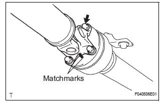
(a) Align the matchmarks on the propeller shaft assembly flange and front flange, and connect the shaft with the 4 bolts, washers and nuts.
Torque: 74 N*m (750 kgf*cm, 54 ft.*lbf)
(b) Check that each joint of the propeller shaft is facing in the correct direction, as shown in the illustration below.
 Inspection
1. INSPECT SPIDER BEARING
(a) Check that the spider bearing moves smoothly by
turning the flange.
(b) Check for the looseness around the joint by strongly
moving the flange in the axial and ...
 Installation
1. INSTALL PROPELLER W/CENTER BEARING SHAFT ASSEMBLY
(a) Align the matchmarks on the propeller shaft
assembly rear flange and differential companion
flange, and connect the shaft with the 4 bol ...
Other materials:
Precaution for cooling fan system
NOTICE: • When the ignition switch is turned off and the
engine temperature is high, the cooling fans may
operate for approximately 3 minutes. • After turning the ignition switch
off, keep hands
and objects away from the fans when they are operating.
HINT:
If all of the following a ...
Engine Coolant Temperature Circuit Range /
Performance Problem
DTC P0116 Engine Coolant Temperature Circuit Range /
Performance Problem
DESCRIPTION
Refer to DTC P0115
DTC No.
DTC Detection Condition
Trouble Area
P0116
ECTs as listed below are nearly same (2 trip detection
logic):
ECT when engine is start ...
Pressure Control Solenoid "D" Performance (Shift
Solenoid Valve SLT)
SYSTEM DESCRIPTION
The linear solenoid valve (SLT) controls the transmission line pressure for
smooth transmission operation
based on signals from the throttle position sensor and the vehicle speed sensor.
The ECM adjusts the
duty ratio (*) of the SLT solenoid valve to control hydraulic line ...
