Toyota Sienna Service Manual: Jam Protection Function Activates During Power Back Door Operation
DESCRIPTION
- It may be caused by ill-fitting back door, faulty touch sensor or faulty pulse sensor.
- The power back door ECU activates the back motor to open / close the power back door, thus controlling the power back door operation. For jam and foreign object detection, the power back door system uses the pulse sensor built into the power back door drive unit and the 2 touch sensors installed in both sides of the back door respectively.
- When either of the touch sensors comes in contact with an object while the back door is closing, the resistance of the touch sensor changes, which is monitored by the power back door ECU. If a change in resistance is detected, the ECU will judge it to be a jam and foreign object detection in the direction that the power back door is moving and reverse back motor rotation. The touch sensors operate only while the back door is closing. They do not operate while the back door is opening.
- The pulse sensor detects changes in the operating speed of the back door while the back door is operating. When the sensor detects a change in the operating speed, the pulse from the sensor also changes, which is monitored by the power back door ECU. If there is a pulse change detected, the ECU will judge it to be a jam and foreign object detection in the direction that the power back door is moving and reverse back motor rotation.
- If a jam and foreign object detection by the touch sensors and the pulse sensor has occurred 2 or more consecutive times and if the 2nd or most recent detection has occurred during closing, then the power back door ECU will cancel automated back door operation and switch the back door to manual operation mode (not electrically controlled). In order to restore the power back door system to normal operation mode, perform either of the following: manually close the back door fully or press the satellite switch for the power back door or the power back door control switch again (reset operation).
WIRING DIAGRAM
INSPECTION PROCEDURE
1 CHECK DTC
- Check for DTC B2222. DTC B2222 indicates a pulse sensor malfunction.
- Without code outputs, proceed to A.
- With code outputs, proceed to B.
2 VISUALLY CHECK
- Check for foreign objects on the operating area.
3 MANUAL OPERATION
- Turn off* the power door main switch in order to locate
the area where reverse operation has been triggered.
* OFF is the condition when the orange paint on the top of the switch does not appear
- Move the back door manually, and then check to make sure no obstacles are present (no extra resistance) around the reverse operation area and that the back door smoothly operates.
4 READ VALUE OF INTELLIGENT TESTER
- Using the intelligent tester, check the DATA LIST for proper functioning of the power back door touch sensor LH.
OK (Power back door ECU):

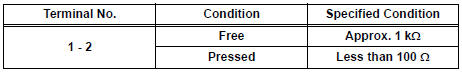
5 INSPECT POWER BACK DOOR TOUCH SENSOR LH
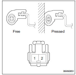
Resistance
6 CHECK WIRE HARNESS (POWER BACK DOOR TOUCH SENSOR LH - POWER BACK DOOR ECU)
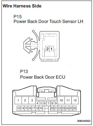
- Disconnect the P15 switch and P13 ECU connectors.
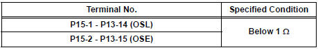
- Check the resistance between the wire harness side connectors.
Resistance (Check for open circuit)
REPLACE POWER BACK DOOR ECU
7 READ VALUE OF INTELLIGENT TESTER
- Using the intelligent tester, check the DATA LIST for proper functioning of the power back door touch sensor RH
OK (Power back door ECU):
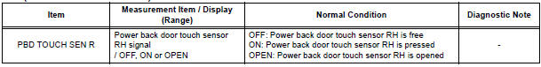
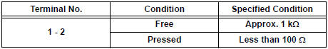
8 CHECK POWER BACK DOOR TOUCH SENSOR RH
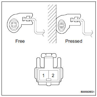
Resistance
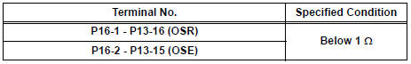
9 CHECK WIRE HARNESS (POWER BACK DOOR TOUCH SENSOR RH - POWER BACK DOOR ECU)
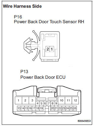
- Disconnect the P16 switch and P13 ECU connectors.
- Check the resistance between the wire harness side connectors.
Resistance (Check for open circuit)
REPLACE POWER BACK DOOR ECU
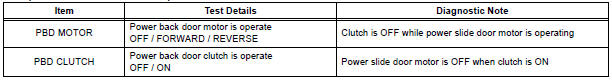
10 PERFORM ACTIVE TEST BY INTELLIGENT TESTER
- Select the ACTIVE TEST and then check that the power back door drive unit operates.
HINT: During the ACTIVE TEST, the intelligent tester sends a signal to the power back door ECU to drive the drive unit.
If the drive unit operates, the drive unit itself and the wire harness between the drive unit and power back door ECU are considered to be functioning normally.
OK (Power back door ECU):
11 INSPECT POWER BACK DOOR DRIVE UNIT
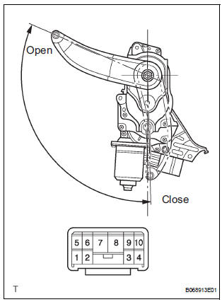
- Remove the unit.
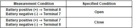
- Connect the battery positive (+) lead to terminal 3 and battery negative (-) terminal lead to terminal 9.
- Apply battery voltage to the terminals and check the motor operation.
OK
- Check the resistance of the clutch terminals.
Resistance
- Reinstall the unit with the connector connected.
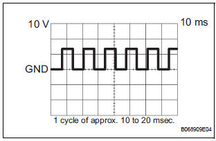
- Check the pulse of the pulse sensor.
- Using an oscilloscope, check the pulse generated when the door is manually opened and closed.
Reference
HINT: A cycle of the pulse changes between approx. 10 to 20 msec. according to the speeds that the slide door is moving.
NOTICE: When disconnecting the drive unit, initialize the power back door system
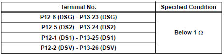
12 CHECK WIRE HARNESS (POWER BACK DOOR DRIVE UNIT - POWER BACK DOOR ECU)
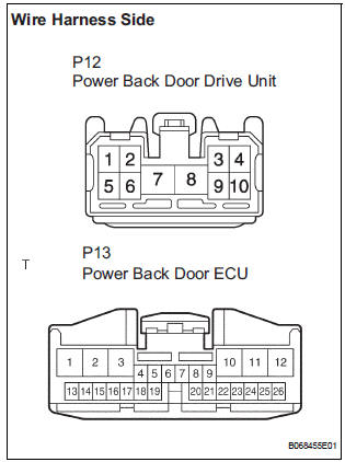
- Disconnect the P12 unit and P13 ECU connectors.
- Check the resistance between the wire harness side connectors.
Resistance (Check for open circuit)
REPLACE POWER BACK DOOR ECU
 Power Back Door does not Operate
DESCRIPTION
The power back door operates only when the power back door main
switch is ON. The power back
door ECU controls the power back door by activating the back door motor
(built into ...
 Power Back Door Warning Buzzer does not Sound
DESCRIPTION
The power back door system uses a warning buzzer built into the
back door, which has 3 ways of
sounding that are used differently according to the situations:
When all the f ...
Other materials:
Diagnosis system
1. CHECK BATTERY VOLTAGE
Standard voltage:
11 to 14 V
If the voltage is below 11 V, recharge the battery before
proceeding.
2. CHECK DLC3
(a) The ECU uses the ISO 15765-4 for communication
protocol. The terminal arrangement of the DLC3
complies with SAE J1962 and matches the ISO
15765-4 f ...
TS and CG Terminal Circuit
DESCRIPTION
In the sensor check mode, a malfunction of the speed sensor that cannot be
detected when the vehicle is
stopped is detected while driving.
Transition to the sensor check mode can be performed by connecting terminals TS
and CG of the DLC3
and turning the ignition switch from off ...
Diagnosis Circuit
DESCRIPTION
DTC output mode is set by connecting terminals TC and CG of the DLC3.
DTCs are displayed by blinking the SRS warning light.
HINT:
When each warning light stays blinking, a ground short in the
wiring of terminal TC of the DLC3 or an
internal ground short in each ECU is ...
