Toyota Sienna Service Manual: Master Reset/ Voice Processing Device ON Error
DTC 01-DD Master Reset
DTC 01-E1 Voice Processing Device ON
DESCRIPTION
|
DTC No. |
DTC Detection Condition |
Trouble Area |
| 01-DD *1 | The device that should be the master has been disconnected after the engine starts. |
|
| 01-E1 *2 | The AMP device records that the AMP output does not function even while the source device is operating. |
HINT:
- *1: This code may be stored if the engine is started and the ignition switch is turned to the START position again.
- *2: Even if no fault is present, this trouble code may be stored depending on the battery condition or engine start voltage.
NOTICE:
- Before starting troubleshooting, be sure to clear DTCs to erase codes stored due to the reasons described in the HINT above. Then, check for DTCs and troubleshoot according to the output DTCs.
- The radio and navigation assembly is the master unit.
- Be sure to clear and recheck DTCs after the inspection is completed to confirm that no DTCs are output.
INSPECTION PROCEDURE
NOTICE: Be sure to read DESCRIPTION before performing the following procedures.
1 CHECK RADIO AND NAVIGATION ASSEMBLY POWER SOURCE CIRCUIT
Refer to the radio and navigation assembly power source circuit.
If the power source circuit is operating normally, proceed to the next step
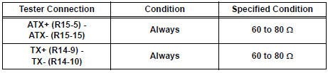
2 INSPECT RADIO AND NAVIGATION ASSEMBLY
- Disconnect the radio and navigation assembly connectors.
- Measure the resistance according to the value(s) in the table below.
Standard resistance
3 IDENTIFY THE COMPONENT WHICH HAS STORED THIS CODE
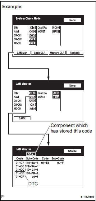
- Enter the diagnostic mode.
- Press the "LAN Mon" switch to change to "LAN Monitor" mode.
- Identify the component which has stored this code.
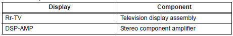
Component Table:
HINT: "NAVI" is the component which has stored this code in the example shown in the illustration.
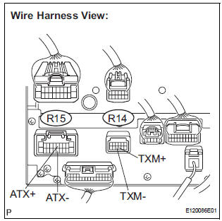
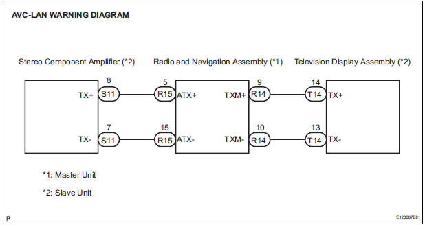
4 CHECK HARNESS AND CONNECT
HINT: For details of the connectors, refer to "TERMINALS OF ECU".
- Referring to the AVC-LAN wiring diagram below, check the AVC-LAN circuit between the radio and navigation assembly and the component which has stored this code.
- Disconnect all connectors between the radio and navigation assembly and the component which has stored this code.
- Check for an open or short in the AVC-LAN circuit between the radio and navigation assembly and the component which has stored this code.
OK: There is no open or short circuit.
5 REPLACE RADIO AND NAVIGATION ASSEMBLY
- Replace the radio and navigation assembly with a normal one and check if the same problem occurs again.
OK: Same problem does not occur.
END
 Transmission Error
DTC 01-DC Transmission Error
DESCRIPTION
DTC No.
DTC Detection Condition
Trouble Area
01-DC
*1
Transmission to component shown by sub-code failed.
(Detec ...
 Master Error
DTC 01-DF Master Error
DESCRIPTION
DTC No.
DTC Detection Condition
Trouble Area
01-DF
*1
The device with a display fails and the master is
switch ...
Other materials:
On-vehicle inspection
1. INSPECT THROTTLE BODY
Listen to the throttle control motor operating sounds.
Turn the ignition switch to the ON position.
When pressing the accelerator pedal position
sensor lever, listen to the running motor. Make
sure that no friction noise comes from the
motor.
...
Actuator check
1. ACTUATOR CHECK
(a) After entering the DTC check mode (Sensor Check
Mode), press the R/F switch.
(b) As each damper, motor and relay automatically
operate actuator check at 1-second intervals from
step No. 1 to No. 10 continuously, check the
temperature and air flow visually and by hand. ...
On-vehicle inspection
1. CHECK POWER MIRROR SWITCH OPERATION
Remote control
The mirror adjust switch can control the adjustment
axis of the mirror surface.
Reverse-linked
This function tilts the mirror surface downward to
improve the visibility when driving in reverse,
provided that all the co ...
