Toyota Sienna Service Manual: Manual Up / Down Function does not Operate on Rear RH Only
DESCRIPTION
If the manual UP/DOWN function does not operate, the power window motor, the regulator switch or the wire harness may be malfunctioning.
WIRING DIAGRAM
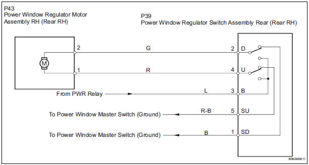
INSPECTION PROCEDURE
1 CHECK WIRE HARNESS (POWER SOURCE)
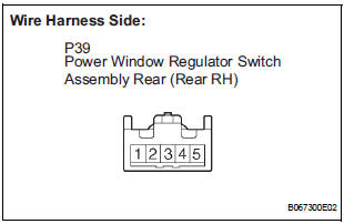
- Disconnect the P39 regulator switch connector.
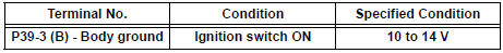
- Turn the ignition switch ON.
- Check the voltage between the terminal 4 of the wire harness side connector and the body ground.
Standard voltage
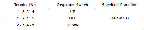
2 INSPECT POWER WINDOW REGULATOR SWITCH (REAR RH)
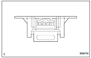
- Remove the regulator switch.
- Check the resistance between the switch terminals when the switch is operated, as shown in the table below.
Standard resistance
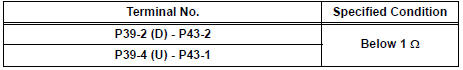
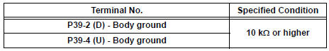
3 CHECK WIRE HARNESS (REGULATOR - MOTOR) (REGULATOR SWITCH - BODY GROUND)
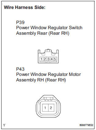
- Disconnect the P43 motor connector.
- Check the resistance between the wire harness side connectors.
Standard resistance
- Check the resistance between the P39 regulator switch connector and body ground.
Standard resistance
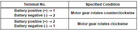
4 INSPECT POWER WINDOW REGULATOR MOTOR ASSEMBLY (REAR RH)
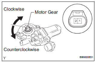
- Remove the motor.
- Apply battery voltage to connector terminals 1 and 2.
- Check that the motor smoothly rotates.
NOTICE: Do not apply battery voltage to any terminals except terminals 1 and 2.
Standard
REPAIR OR REPLACE HARNESS AND CONNECTOR (MASTER SWITCH - REGULATOR SWITCH)
 Manual Up / Down Function does not Operate on Rear LH Only
DESCRIPTION
If the manual UP/DOWN function does not operate, the power window motor, the
regulator switch or the
wire harness may be malfunctioning.
WIRING DIAGRAM
INSPECTION PROCEDURE
1 CH ...
 Power Windows do not Operate at All
DESCRIPTION
If all of the door windows do not operate, no power may be supplied to the
power window master switch or
the power window master switch itself may have a malfunction.
WIRING DIAGRAM
...
Other materials:
Identification information
VEHICLE IDENTIFICATION AND SERIAL NUMBERS
1. VEHICLE IDENTIFICATION NUMBER
(a) The vehicle identification number is stamped on the
vehicle identification number plate and the
certification label, as shown in the illustration.
A:
Vehicle Identification Number Plate
B:
...
Using a flatbed truck
If you use chains or cables to tie
down your vehicle, the angles
shaded in black must be 45.
Do not overly tighten the tie
downs or the vehicle may be damaged.
WARNINGObserve the following precautions.
Failure to do so may result in death or serious injury.
When tow ...
Display Panel does not Open, Tilt or Tilts Improperly
INSPECTION PROCEDURE
1 CHECK RADIO AND NAVIGATION ASSEMBLY
Check for foreign matter or obstructions caught in the
moving parts of the panel.
OK:
No obstruction or foreign matter found.
2 CHECK OPERATION
Check if the navigation and audio systems function
properly.
OK:
Naviga ...
