Toyota Sienna Service Manual: Map Disc Read Error
DTC 58-42 Map Disc Read Error
DTC 80-42 Map Disc Read Error
DESCRIPTION
|
DTC No. |
DTC Detection Condition |
Trouble Area |
| 58-42 |
|
|
| 80-42 |
|
INSPECTION PROCEDURE
HINT: After the inspection is completed, clear the DTCs.
1 CHECK MAP DISC
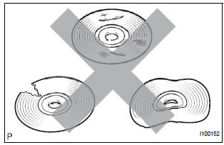
- Check that the map disc is not deformed or cracked.
OK: No deformations or cracks on the map disc.
2 DISC CLEANING
- Disc cleaning
- If dirt is on the disc surface, wipe it clean with a soft cloth from the inside to the outside in a radial direction.
NOTICE: Do not use a conventional record cleaner or anti-static preservative.
3 DTC CLEAR AND RECHECK
- Clear the DTCs
- Recheck for DTCs and check if the same trouble occurs again.
OK: Same problem does not occur.
4 REPLACE MAP DISC
- Replace the map disc.
- Clear the DTCs and recheck for DTCs.
- Check if the same trouble occurs again.
OK: Same problem does not occur
REPLACE RADIO AND NAVIGATION ASSEMBLY
 GPS Antenna Error/ GPS Antenna Power Source Error
DTC 58-40 GPS Antenna Error
DTC 58-41 GPS Antenna Power Source Error
DTC 80-40 GPS Antenna Error
DTC 80-41 GPS Antenna Power Source Error
DESCRIPTION
DTC No.
DTC Detection Condi ...
 SPD Signal Error
DTC 58-43 SPD Signal Error
DTC 80-43 SPD Signal Error
DESCRIPTION
DTC No.
DTC Detection Condition
Trouble Area
58-43
A difference between the GPS speed and SPD ...
Other materials:
On-vehicle inspection
1. CHECK SEAT HEATER CONTROL (WIRE HARNESS
SIDE)
Disconnect the connector from the seat heater
control.
Measure the voltage and resistance of each
terminal of the wire harness side connector.
Standard
If the result is not as specified, there may be a
malfunction on ...
System Too
DESCRIPTION
The fuel trim is related to the feedback compensation value, not to the basic
injection time. The fuel trim
consists of both the short-term and long-term fuel trims.
The short-term fuel trim is fuel compensation that is used to constantly
maintain the air-fuel ratio at
stoich ...
Diagnostic trouble code chart
HINT:
If a trouble code is displayed during the DTC check, inspect
the circuit listed for that code. For details of each code, refer
to the relevant page listed under respective "DTC No." in the
DTC chart.
TIRE PRESSURE WARNING SYSTEM:
...
