Toyota Sienna Service Manual: Navigation system
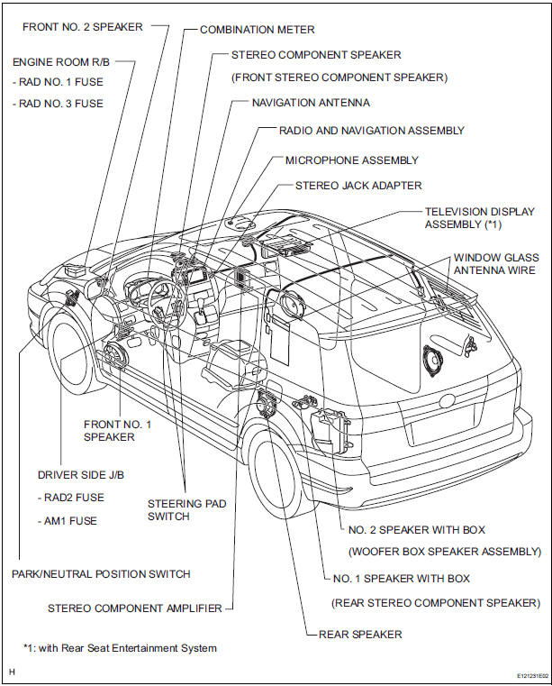
PARTS LOCATION
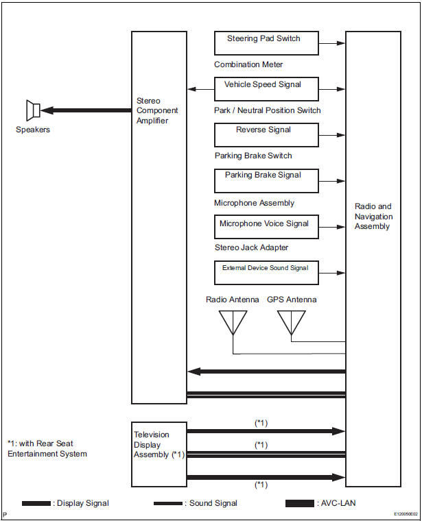
SYSTEM DIAGRAM
- System description
- How to proceed with troubleshooting
- Identification of noise source
- System normal condition check
- Display check mode
- Bluetooth tel check mode
- Navigation check mode
- Diagnosis display detailed description
- Problem symptoms table
- Terminals of ECU
- DTC check / clear
- Diagnostic trouble code chart
 Navigation
...
 System description
1. Radio and navigation assembly outline
Conventionally, 2 separate devices, a "radio and
display" and a "navigation ECU" are used. This
model has adopted a new type, ...
Other materials:
Transponder Chip Malfunction
DTC B2793 Transponder Chip Malfunction
DESCRIPTION
This DTC is output when a malfunction is found in the key during the key code
registration or the key code
is not registered normally. Replace the key when the key code registration is
not performed normally and
this DTC is detected.
IN ...
Key Lock-in Prevention Function does not Work Properly (Manual
Operation and Operation Interlocked with Key are Active)
DESCRIPTION
The un-lock warning switch turns ON when the key is inserted in the ignition
key cylinder. The courtesy
light switch turns ON when the driver side door is opened. These 2 switches are
monitored by the body
ECU.
In order to prevent the key from being locked in, the body ECU cont ...
Heated oxygen sensor (for 2wd)
Components
Removal
1. DISCONNECT CABLE FROM NEGATIVE BATTERY
TERMINAL
CAUTION:
Wait at least 90 seconds after disconnecting the
cable from the nagative (-) battery terminal to
prevent airbag and seat belt pretensioner activation.
2. REMOVE HEATED OXYGEN SENSOR (for Bank ...
