Toyota Sienna Service Manual: Meter Illumination does not Dim at Night
DESCRIPTION
- Confirm that the vehicle is equipped with the optitron meter, then check this circuit.
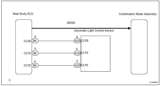
- The combination meter assembly receives a auto dimmer signal from the body ECU by the multiplex communication line.
WIRING DIAGRAM
INSPECTION PROCEDURE
1 CHECK MULTIPLEX COMMUNICATION SYSTEM
- Check if MULTIPLEX communication DTC is output
Result

2 CHECK DTC
- Check if the DTC B1244 is output
Result

3 PERFORM ACTIVE TEST BY INTELLIGENT TESTER
- Operate the intelligent tester according to the steps on the display and select "DATA LIST".
MAIN BODY

OK: The meter illumination is dimmed when the DIMMER SIG is ON.
CHECK LIGHTING SETTING
4 REPLACE COMBINATION METER ASSEMBLY
OK: The operation of the combination meter assembly returns to normal.
END
 Meter Illumination is Always Dark
DESCRIPTION
Confirm that the vehicle is equipped with the optitron meter, then
check this circuit.
The combination meter assembly receives a auto dimmer signal from the
body ECU by t ...
 Combination meter
COMPONENTS
...
Other materials:
DTC check / clear
1. USING INTELLIGENT TESTER
Hook up the intelligent tester to the DLC3.
Monitor the ECU data by following the prompts on
the tester screen.
HINT:
intelligent tester has "Snapshot" function which
records the monitored data. Please refer to the
intelligent tester op ...
GPS Antenna Error/ GPS Antenna Power Source Error
DTC 58-40 GPS Antenna Error
DTC 58-41 GPS Antenna Power Source Error
DTC 80-40 GPS Antenna Error
DTC 80-41 GPS Antenna Power Source Error
DESCRIPTION
DTC No.
DTC Detection Condition
Trouble Area
58-40
GPS antenna error
Wire harness
GPS ...
Removal
1. BOLT, SCREW AND NUT TABLE
The bolts, the screws and the nuts, which are
necessary for installation and removal of the
instrument panel are shown in the illustration below
with alphabets.
2. DISCONNECT BATTERY NEGATIVE TERMINAL
3. REMOVE STEERING WHEEL COVER LOWER NO.2
4. ...
