Toyota Sienna Service Manual: Torque Converter Clutch Solenoid Circuit
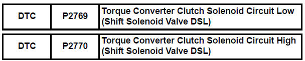
DESCRIPTION
The shift solenoid valve DSL is turned "ON" and "OFF" by signals from the ECM
in order to control the
hydraulic pressure operation, the lock-up relay valve, which then controls
operation of the lock-up clutch.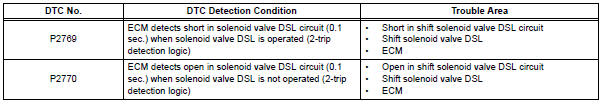
MONITOR DESCRIPTION
Torque converter lock-up is controlled by the ECM based on engine rpm, engine load, engine temperature, vehicle speed, transmission temperature, and shift range selection. The ECM determines the lock-up status of the torque converter by comparing the engine rpm (NE) to the input turbine rpm (NT).
The ECM calculates the actual transmission gear by comparing input turbine rpm (NT) to counter gear rpm (NC). When conditions are appropriate, the ECM requests "lock-up" by applying control voltage to the shift solenoid DSL. When the DSL is opened, it applies pressure to the lock-up relay valve and locks the torque converter clutch. If the ECM detects an open or short in the DSL solenoid circuit, the ECM interprets this as a fault in the DSL solenoid or circuit. The ECM will turn on the MIL and store the DTC.
MONITOR STRATEGY
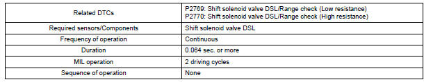
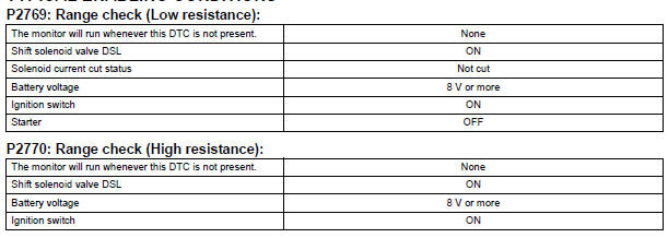
TYPICAL ENABLING CONDITIONS

TYPICAL MALFUNCTION THRESHOLDS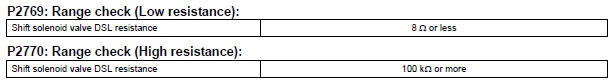
COMPONENT OPERATING RANGE
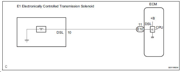
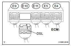
WIRING DIAGRAM
INSPECTION PROCEDURE
1 INSPECT TRANSMISSION WIRE (DSL)
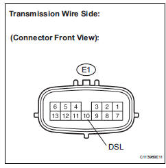
(a) Disconnect the transmission wire connector from the transaxle.
(b) Measure the resistance according to the value(s) in the table below.
Standard resistance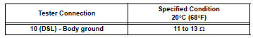

2 CHECK HARNESS AND CONNECTOR (TRANSMISSION WIRE - ECM)
(a) Connect the transmission wire connector.
(b) Disconnect the ECM connector.
(c) Measure the resistance according to the value(s) in the table below.
Standard resistance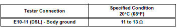

REPLACE ECM
3 INSPECT SHIFT SOLENOID VALVE DSL
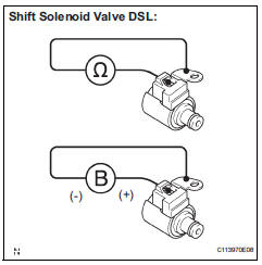
(a) Remove the shift solenoid valve DSL.
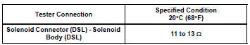
(b) Measure the resistance according to the value(s) in the table below.
Standard resistance
(c) Connect the positive (+) lead to the terminal of the solenoid connector, and the negative (-) lead to the solenoid body.
OK: The solenoid valve makes an operating sound.

REPAIR OR REPLACE TRANSMISSION WIRE
 Pressure Control Solenoid "D" Electrical (Shift
Solenoid Valve SLT)
Pressure Control Solenoid "D" Electrical (Shift
Solenoid Valve SLT)
DESCRIPTION
The linear solenoid valve (SLT) controls the transmission line pressure for
smooth transmission operation
based on signals from the throttle position sensor and the vehicle speed senso ...
Other materials:
Inspection
1. Inspect pack clearance of reverse clutch
(A) install the intermediate shaft and needle roller
bearing onto the transaxle rear cover.
(B) using a dial indicator, measure the reverse clutch
pack clearance while applying and releasing
compressed air (392 kpa, 4.0 Kgf/cm2, 57 psi).
Pack c ...
Low Battery Positive Voltage
DTC C1241/41 Low Battery Positive Voltage
DESCRIPTION
If there is a problem with the brake actuator assembly (skid control ECU)
power supply circuit, the skid
control ECU outputs the DTC and prohibits the ABS operation with the fail safe
function.
If the voltage supplied to the IG1 termina ...
Installation
1. INSTALL BRAKE ACTUATOR
(a) Install the brake actuator assembly with the 2 nuts.
Torque: 5.4 N*m (55 kgf*cm, 48 in.*lbf)
2. INSTALL BRAKE ACTUATOR WITH BRACKET
(a) Install the actuator with bracket with the 3 bolts.
Torque: 20 N*m (199 kgf*cm, 14 ft.*lbf)
NOTICE:
Be careful not to dam ...
