Toyota Sienna Service Manual: Installation
1. INSTALL TRANSMISSION WIRE
(a) Coat the O-ring of the transmission wire connector with ATF and install it.
(b) Install the transmission wire with the bolt.
Torque: 5.4 N*m (55 kgf*cm, 48 ft.*lbf)
2. CONNECT TRANSMISSION WIRE
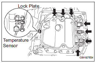
(a) Coat the O-ring of the ATF temperature sensor with ATF.
(b) Install the ATF temperature sensor with the lock plate and bolt.
Torque: 6.6 N*m (67 kgf*cm, 58 ft.*lbf) (c) Connect the 7 shift solenoid valve connectors.
3. INSTALL AUTOMATIC TRANSAXLE OIL PAN SUBASSEMBLY
(a) Install the 2 magnets in the oil pan.
(b) Apply seal packing to the 18 bolts.
Seal packing: THREE BOND 2430 or equivalent
(c) Using a new gasket, install the oil pan to the transaxle case with the 18 bolts.
Torque: 7.8 N*m (80 kgf*cm, 69 in.*lbf)
| NOTICE: Apply seal packing to the bolts and tighten them within 10 minutes of application. |
4. CONNECT CABLE TO NEGATIVE BATTERY TERMINAL
5. ADD AUTOMATIC TRANSAXLE FLUID
6. INSPECT AUTOMATIC TRANSAXLE FLUID (See page AX-123)
7. INSTALL ENGINE UNDER COVER NO.1
8. RESET MEMORY
HINT: (See page AX-16)
 Removal
1. DISCONNECT CABLE FROM NEGATIVE BATTERY
TERMINAL
2. REMOVE ENGINE UNDER COVER NO.1
3. DRAIN AUTOMATIC TRANSAXLE FLUID
(a) Remove the drain plug and gasket, and drain the
ATF.
(b) Install a n ...
 Valve body assembly
Components
...
Other materials:
Adjustment
1. INSPECT SHIFT LEVER POSITION
(a) When shifting from P to R position only with ignition
switch ON and brake pedal, make sure that the
shifting lever moves smoothly and can be
moderately operated.
(b) When starting engine, make sure that the vehicle
moves forward when shifting from N to D p ...
Display check mode
HINT:
This mode checks the color display on the display.
Illustrations may differ from the actual vehicle depending
on the device settings and options. Therefore, some
detailed areas may not be shown exactly the same as on
the actual vehicle.
1. ENTER DIAGNOSTIC MODE
2. D ...
Removal
1. REMOVE FRONT EXHAUST PIPE ASSEMBLY
HINT:
(See page EX-8)
2. REMOVE PROPELLER WITH CENTER BEARING
SHAFT ASSEMBLY
HINT:
(See page PR-3)
3. REMOVE REAR DIFFERENTIAL FILLER PLUG
(a) Using a hexagon wrench (10 mm), remove the filler
plug and gasket.
4. REMOVE REAR DIFFERENTIAL DRAIN PLUG
(a ...
